Switch valve controlled by pilot valve sleeves

A pilot valve, on-off valve technology, applied in the direction of fluid pressure actuation device, servo motor assembly, mechanical equipment, etc., can solve the problem of unable to overcome the hydraulic force to push the valve core, increase the size of the on-off valve, increase the complexity, etc. Improve the ability to resist external disturbances, reduce the size, and reduce the effect of control power

Active Publication Date: 2019-03-29
ZHONGHONG VALVE CO LTD
View PDF9 Cites 5 Cited by
  • Summary
  • Abstract
  • Description
  • Claims
  • Application Information

AI Technical Summary

Problems solved by technology

For fluid control valves with medium and large flow rates, since the hydraulic force acting on the valve core is too large when the valve core is opened, it is still impossible to overcome the hydraulic force to push the valve core simply by increasing the volume of the electromagnetic drive device.
So the current technology is: use a small electromagnetic switch valve (usually 6-way through) as the pilot stage, control the pressure of the left and right chambers of the valve core, and realize the hydraulic power to push the valve core, which solves the problem of large flow down-changing However, this technology not only increases the volume of the switch valve, but also increases the cost. The superposition of the two valves also increases the complexity of the valve and reduces the reliability of the valve.

Method used


Image

  • Switch valve controlled by pilot valve sleeves
  • Switch valve controlled by pilot valve sleeves
  • Switch valve controlled by pilot valve sleeves

Examples


Embodiment Construction

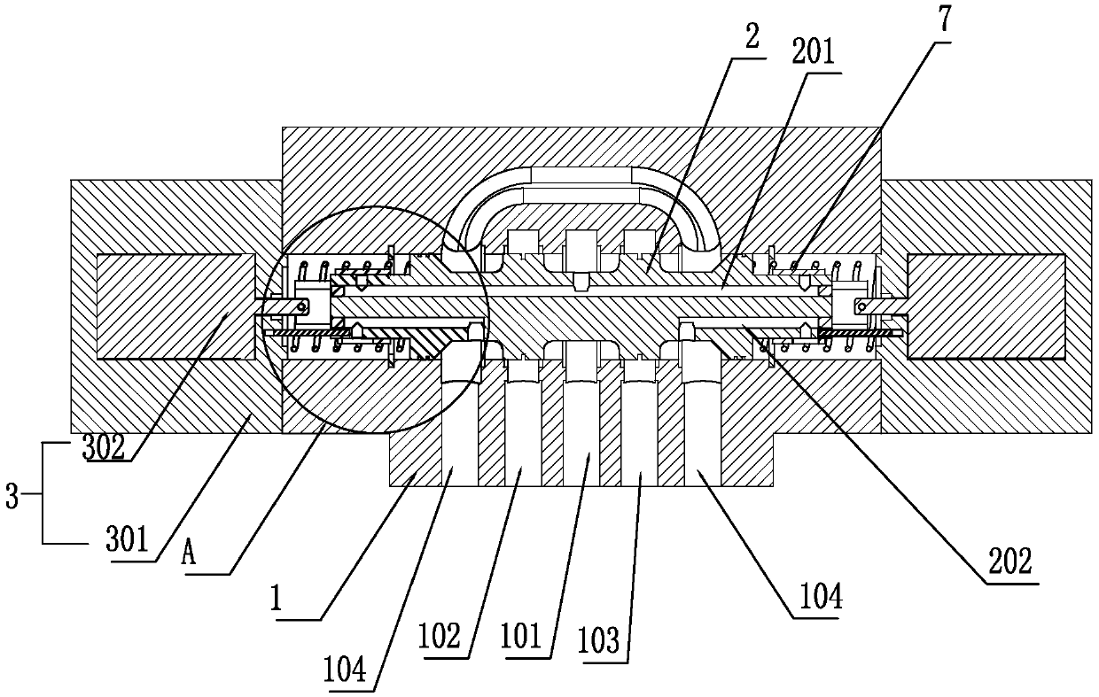
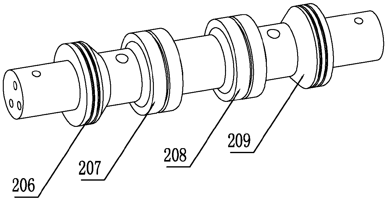
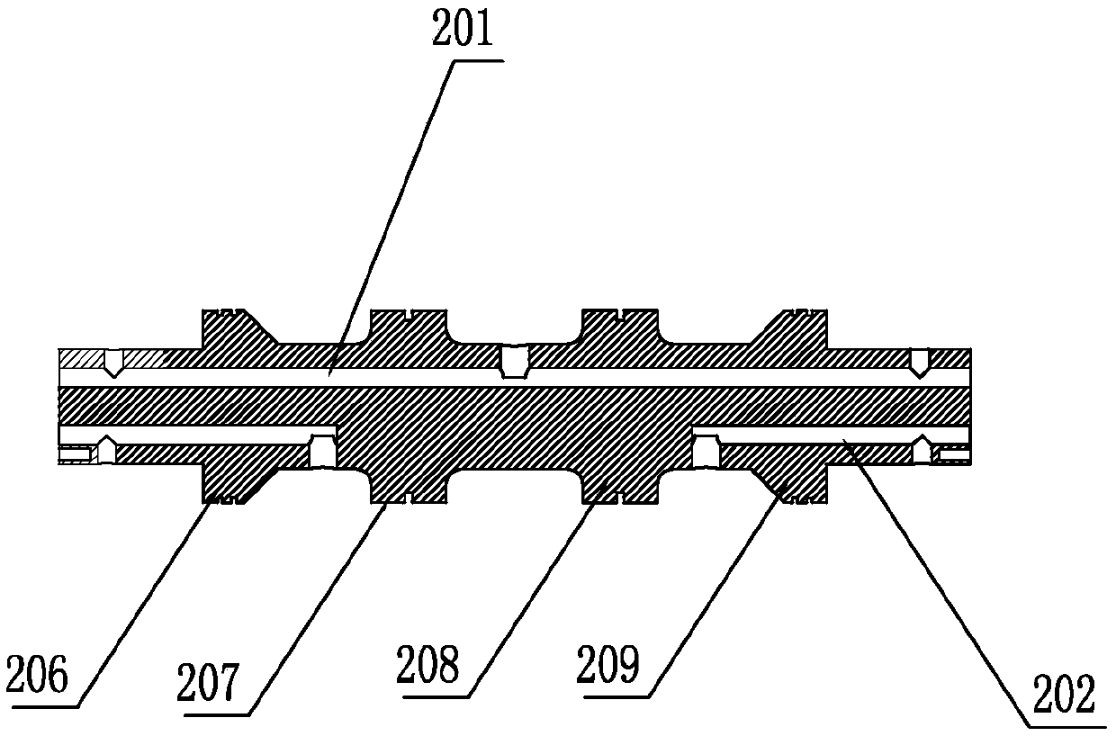
[0022] In order to make the object, technical solution and advantages of the present invention clearer, the present invention will be further described in detail below in conjunction with the accompanying drawings.

[0023] It should be noted that all expressions using "first" and "second" in the embodiments of the present invention are to distinguish two entities with the same name but different parameters or parameters that are not the same, see "first" and "second" It is only for the convenience of expression, and should not be construed as a limitation on the embodiments of the present invention, which will not be described one by one in the subsequent embodiments.

[0024] The terms of direction and position mentioned in the present invention, such as "up", "down", "front", "back", "left", "right", "inside", "outside", "top", "bottom" ", "side", etc., are only referring to the direction or position of the drawings. Therefore, the terms used in direction and position are ...


PUM


Abstract

The invention belongs to the field of fluid transmission and control, and specifically relates to a switch valve controlled by pilot valve sleeves. The switch valve controlled by the pilot valve sleeve comprises a valve body and a main valve element, wherein a drive device is arranged at the two ends of the valve body separately; an adjustment cavity is formed between each drive device and the main valve element; an oil inlet channel and an oil outlet channel which communicate with the adjustment cavities are formed in the main valve element; the pilot valve sleeves connected with the drive devices sleeve outside the main valve element; and the drive devices drive so that the pilot valve sleeves circumferentially rotate relative to the main valve element to close the oil inlet channel andopen the oil outlet channel or open the oil inlet channel and close the oil outlet channel, so that the pressure difference of the two ends of the main valve element is changed. Compared with an original single-stage valve used for a low flow rate, the specifications and dimensions of the electromagnetic drive devices are reduced, the overall weight and installation dimensions are reduced, the needed control power is reduced, the capacity of resisting to external disturbance of the whole valve is improved, and more stable performance is achieved. Compared with an original single-stage valve used for medium and high flow rates, the weight and installation dimensions of the whole fluid control valve can be greatly reduced, the parts are reduced, and the stability of the valve is further improved.

Description

technical field [0001] The invention belongs to the field of fluid transmission and control, and in particular relates to a pilot valve sleeve control on-off valve. Background technique [0002] Fluid control valves, especially hydraulic valves, play the role of controlling flow, pressure and switching oil circuits. For example, the electromagnetic switching valve plays the role of controlling the flow and switching the oil circuit; the electromagnetic switching valve is divided into: single-stage valve (direct acting valve) and two-stage valve (pilot control valve) according to the flow capacity. In the industry standard, single-stage valves (direct-acting valves) are divided into 6 channels and 10 channels; two-stage valves (pilot control valves) are divided into 16, 25, 32... channels (the larger the number The larger the valve volume, the greater the flow capacity). [0003] The fluid switching control valve used for small flow is generally in the form of a single-stag...

Claims


Application Information

Patent Timeline
Patent Type & Authority Applications(China)
IPC IPC(8): F15B13/02
CPCF15B13/02
Inventor 任燕汤何胜向家伟周余庆钟永腾蒋勇英孙维方
Owner ZHONGHONG VALVE CO LTD
Why Eureka
Try Eureka