
Water cooling motor

A water-cooled motor and motor housing technology, applied in electrical components, electromechanical devices, electric components, etc., can solve the problems of limited and complex motor structure, and achieve the effects of reducing manufacturing and assembly costs, long service life, and stable materials

Pending Publication Date: 2019-03-29
南京沃特电机有限公司 +1
View PDF1 Cites 1 Cited by
  • Summary
  • Abstract
  • Description
  • Claims
  • Application Information

AI Technical Summary

Problems solved by technology

In this technical solution, it is the water-cooling cavity that absorbs heat, and the water-cooling cavity is only in partial contact with the motor housing, so the heat dissipation effect and speed are effective. The main role of the S-shaped water outlet pipe in this technical solution is still as the water pipe itself In use, although it also undertakes a certain heat dissipation effect, the S-shaped water outlet pipe does not directly contact the motor housing, that is, the water in the S-shaped water outlet pipe does not directly exchange heat with the housing, and the water in the S-shaped water outlet pipe has already It is the hot water flowing out of the water-cooling chamber, which conducts the heat of the shell through the ribs and dissipates heat through the S-shaped water outlet pipe fittings, which is more limited
At the same time, the water cooling chamber and the S-shaped water outlet pipe are large components added to the motor, which makes the structure of the motor complex

Method used


Image

  • Water cooling motor
  • Water cooling motor
  • Water cooling motor

Examples


Embodiment Construction

[0029] It is easy to understand that, according to the technical solution of the present invention, those skilled in the art can imagine various implementations of the present invention without changing the essence and spirit of the present invention. Therefore, the following specific embodiments and drawings are only exemplary descriptions of the technical solution of the present invention, and should not be regarded as the entirety of the present invention or as a limitation or limitation on the technical solution of the present invention.

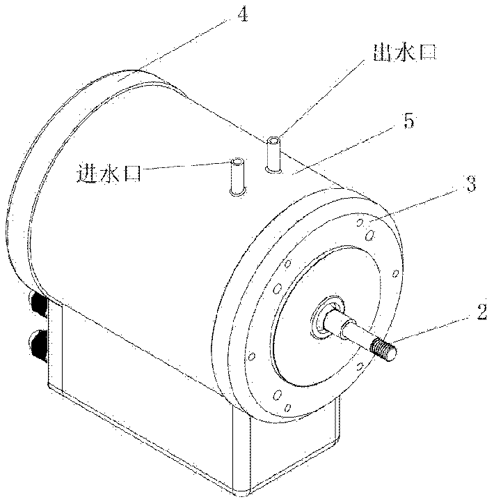
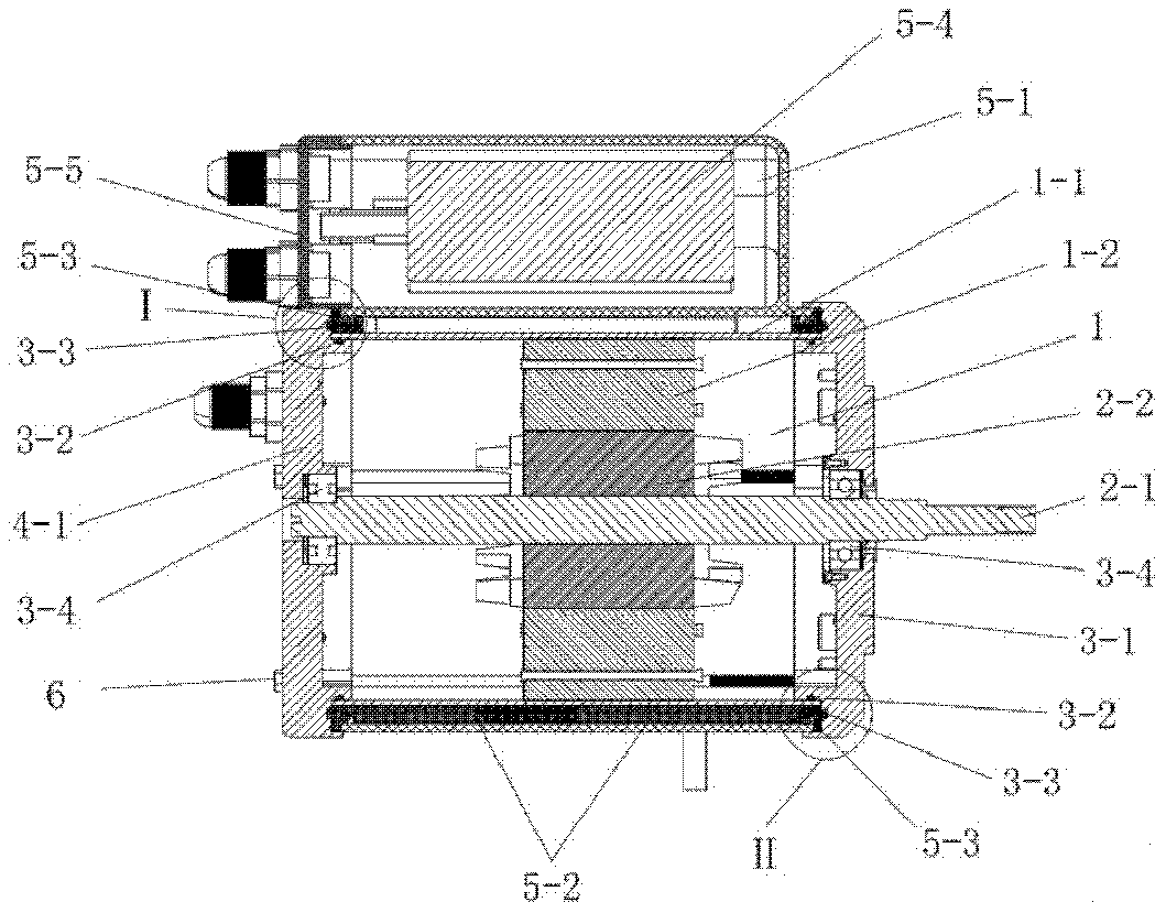
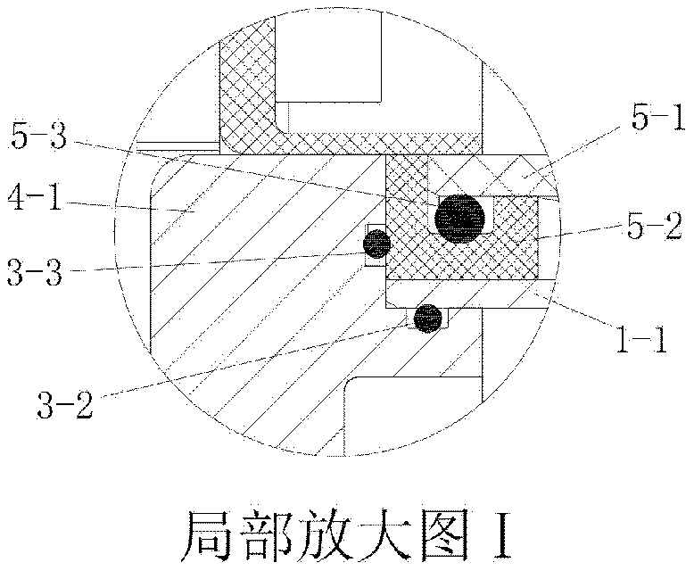
[0030] combine figure 1 , The water-cooled motor shown in this embodiment includes a stator assembly 1 , a rotor assembly 2 , a front end cover assembly 3 , a rear end cover assembly 4 , an outer cylinder assembly 5 , and bolts 6 .

[0031] The stator assembly 1 includes an inner cylinder 1-1 and a stator coil assembly 1-2 located inside the inner cylinder 1-1, both of which are fastened and fixed by tooling;

[0032] The rotor assembly...


PUM


Abstract

The invention relates to a water cooling motor. The water cooling motor includes a stator coil assembly and a rotor assembly, and includes an inner cylinder and an outer cylinder, wherein the stator coil assembly and the rotor assembly are arranged in the inner cylinder; the inner cylinder is arranged outside the outer cylinder; a cooling water channel is arranged between the inner cylinder and the outer cylinder; the cooling water channel is formed by the inner cylinder, the outer cylinder and a water channel member; a cavity is formed between the outer wall of the inner cylinder and the inner wall of the outer cylinder; a continuous S-shaped channel is arranged on the water channel member; and the water channel member is arranged between the inner cylinder and the outer cylinder, and theinner and outer walls of the water channel member are in sealed coordination with the outer wall of the inner cylinder and the inner wall of the outer cylinder respectively, so as to form a cooling water channel limited by the S-shaped channel between the outer wall of the inner cylinder and the inner wall of the outer cylinder. The water cooling motor has the advantages of simple structure, preferable water cooling effect, and high reliability, can reduce the cost of manufacturing and assembling, and can prolong the service life of the motor.

Description

technical field [0001] The invention belongs to the technical field of motors, and in particular relates to a water-cooled motor. Background technique [0002] The motor will generate a certain amount of heat during the working process, which will cause the temperature inside the motor to rise. Therefore, when working for a long time, if the heat of the motor is large, the temperature inside the motor will be too high and the circuit of the motor will be damaged. Damage occurs and the motor needs to be cooled. In the prior art, air-cooled motors are generally used to cool down, but the manufacturing costs of air-cooled motors are high and the noise is large. A small number of motors also use water cooling to cool down, but the structure is complex, the life is short, the stability is poor, and the cost is high. For example, the invention patent application with application number 201810704338.3 discloses a water-cooled motor, which is used to take away heat from the motor ...

Claims


Application Information

Patent Timeline
Patent Type & Authority Applications(China)
IPC IPC(8): H02K9/19H02K5/20
CPCH02K5/20H02K9/19
Inventor 孙网生
Owner 南京沃特电机有限公司
Learn More