Signal processing method based on quasi high-order square spectrum

A signal processing and high-frequency signal technology, applied in baseband system, baseband system components, shaping network in transmitter/receiver, etc., can solve problems such as maintenance, discrete spectral line weak calculation complexity, etc. The effects of strong features, slow attenuation of spectral line features, and high engineering application value

Active Publication Date: 2019-03-29
XIDIAN UNIV
4 Cites 0 Cited by

AI-Extracted Technical Summary

Problems solved by technology

The invention not only maintains the discrete spectral line characteristics of the high-order power spectrum of the signal, but also solves the problem of the weaker discrete spectra...

Abstract

The invention discloses a signal processing method based on a quasi high-order square spectrum. The signal processing method based on the quasi high-order square spectrum comprises the steps of: (1),obtaining a time-domain complex baseband signal; (2), obtaining an envelope sequence and a phase sequence of the time-domain complex baseband signal; (3), obtaining a quasi high-order square signal; (4), obtaining the quasi high-order square spectrum of the time-domain complex baseband signal; and (5), obtaining the spectrum refined quasi high-order square spectrum of the time-domain complex baseband signal. According to a quasi high-order square spectrum calculation method adopted in the invention, the spectral line characteristics of the traditional high-order square spectrum are reserved; furthermore, the operation complexity of calculating the high-order square spectrum is greatly reduced; the spectral line characteristic detection performance of the high-order square spectrum is improved; and thus, the identification performance of the high-order square spectrum in the modulation identification aspect is improved. According to the signal processing method based on the quasi high-order square spectrum disclosed by the invention, a spectrum refining method is adopted at the same time; a spectrum near the spectrum line characteristics is refined; therefore, the spectrum distinguishing rate is increased; and the estimation performance of the high-order square spectrum in frequency offset and baud rate estimation aspects is improved.

Application Domain

Modulation type identificationCarrier regulation +1

Technology Topic

Image

  • Signal processing method based on quasi high-order square spectrum
  • Signal processing method based on quasi high-order square spectrum
  • Signal processing method based on quasi high-order square spectrum

Examples

  • Experimental program(1)

Example Embodiment

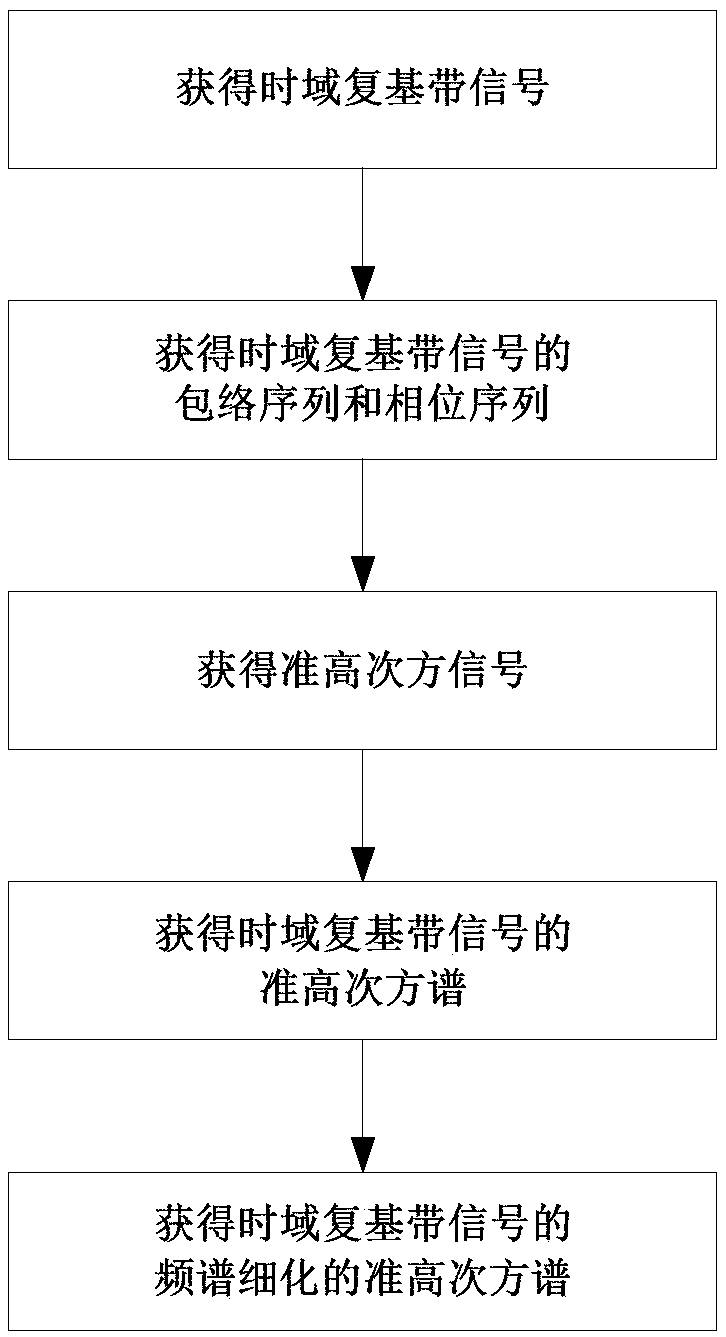
[0032] The present invention will be further described below in conjunction with the drawings.
[0033] Reference attached figure 1 The specific steps of the implementation of the present invention are described as follows.
[0034] Step 1. Obtain a time-domain complex baseband signal.
[0035] The analog-to-digital conversion module of the wireless communication signal processing receiver is used to convert the radio frequency analog signal received by the radio frequency antenna into a time domain high frequency signal.
[0036] In the field of non-cooperative communication, the center frequency of the time-domain high-frequency signal is obtained by using the center of gravity estimation formula, and in the field of cooperative communication, the center frequency of the time-domain high-frequency signal is obtained according to the cooperative communication protocol.
[0037] In the field of non-cooperative communication, use the following formula to obtain the center frequency of the time domain high frequency signal:
[0038]
[0039] Where f c Represents the center frequency of the time domain high frequency signal, ∑ represents the summation operation, M represents the total number of elements in the time domain high frequency signal spectrum, l represents the number of the elements in the time domain high frequency signal spectrum, and the value of l is greater than or equal to 1. And a positive integer less than or equal to M, f l Represents the frequency corresponding to the lth element in the time domain high frequency signal spectrum, |·| represents the absolute value operation, Y l Represents the lth element in the time domain high frequency signal spectrum.
[0040] The cooperative communication protocol means that the center frequency of the time-domain high-frequency signal is known to both parties.
[0041] According to the center frequency of the time-domain high-frequency signal, the coherent demodulation method is used to digitally down-convert the time-domain high-frequency signal to obtain a time-domain complex baseband signal.
[0042] Step 2: Obtain the envelope sequence and phase sequence of the time-domain complex baseband signal.
[0043] Take the absolute value of each element in the time domain complex baseband signal in turn, and compose the envelope sequence of the time domain complex baseband signal by the absolute values ​​of all elements.
[0044] Using the complex phase formula, the phase of each element in the time-domain complex baseband signal is obtained in turn, and the phases of all elements are combined into the phase sequence of the time-domain complex baseband signal.
[0045] The phase sequence of the time-domain complex baseband signal is obtained by the following formula:
[0046]
[0047] Where θ i Represents the phase of the i-th element in the time-domain complex baseband signal, θ i The value range of is [-π,π], i represents the sequence number of the element in the time-domain complex baseband signal, the value of i is a positive integer, arctan(·) represents the arctangent operation, Q i Represents the imaginary part of the i-th element in the time-domain complex baseband signal, I i Represents the real part of the i-th element in the time-domain complex baseband signal.
[0048] Step 3. Obtain the quasi-high power signal.
[0049] Use the following quasi-high-power signal formula to calculate the quasi-high-power signal:
[0050]
[0051] Where u k Represents the k-th element in the quasi-high power signal, the value of k is greater than 0 and less than or equal to the total number of elements in the time-domain complex baseband signal, B m Represents the m-th element in the envelope sequence of the time-domain complex baseband signal, e (·) Represents the exponential operation based on the natural constant e, j represents the imaginary unit symbol, N represents the power of the quasi-high power signal, and its value is a positive integer greater than 0, φ n Represents the nth element in the phase sequence of the time-domain complex baseband signal, and the values ​​of k, m, and n are correspondingly equal.
[0052] Step 4. Obtain the quasi-high power spectrum of the time-domain complex baseband signal.
[0053] Using the power spectrum estimation method, the obtained power spectrum of the higher power signal is used as the quasi-high power spectrum of the time-domain complex baseband signal, wherein the application scenario of the quasi-high power spectrum is the same as that of the high power spectrum.
[0054] The power spectrum estimation method refers to any one of the correlation diagram method, the periodogram method, the Welch spectrum estimation method, the AR spectrum estimation method, and the Burg spectrum estimation method.
[0055] Application scenarios refer to scenarios that can be applied to blind recognition of modulation signals, baud rate estimation, and frequency offset estimation.
[0056] Step 5: Obtain the refined quasi-high power spectrum of the time domain complex baseband signal.
[0057] Traverse each element in the quasi-high power spectrum of the time-domain complex baseband signal in turn, take the element greater than the adjacent element as the maximum value, and arrange all the maximum values ​​from large to small to obtain the time-domain complex baseband signal The characteristic sequence of discrete spectral lines of the quasi-high power spectrum.
[0058] Using the spectral line highlighting index formula, calculate the spectral line highlighting index sequence.
[0059] The sequence of the spectral line highlight index is obtained by the following formula:
[0060]
[0061] Where γ K Represents the Kth element in the spectral line prominence index sequence, the value of K is a positive integer, p represents the number of the element in the discrete spectral line characteristic sequence of the quasi-high power spectrum of the time-domain complex baseband signal, and the value of p is a positive integer, H p It is the p-th element in the discrete spectral line characteristic sequence of the quasi-high power spectrum of the time-domain complex baseband signal.
[0062] Find the element number corresponding to the maximum value in the spectral line protruding index sequence as the number of discrete spectral line feature protruding P of the quasi-high power spectrum of the time-domain complex baseband signal.
[0063] The first P elements in the discrete spectral line feature sequence of the quasi-high power spectrum of the time-domain complex baseband signal are formed into a discrete spectral line feature highlight sequence, and the frequency corresponding to each element in the discrete spectral line feature highlight sequence is sequentially found to form The discrete spectral line feature highlights the frequency sequence.
[0064] The spectral refinement method is used to refine the quasi-high power spectrum of the time-domain complex baseband signal near the frequency of the discrete spectral line features, and obtain the refined quasi-high power spectrum of the time-domain complex baseband signal.
[0065] The spectrum refinement method refers to any one of the Chirp-Z transform spectrum refinement method or the ZoomFFT spectrum refinement method.
[0066] The technical effects of the present invention will be further explained below in conjunction with simulation experiments.
[0067] 1. Simulation conditions:
[0068] The simulation experiment of the present invention uses Matlab R2014a software, the digital modulation mode is binary phase shift keying BPSK, the forming function is raised cosine roll-off forming, the forming coefficient is 0.35, the modulation signal baud rate is 1MBuad, the received signal sampling rate is 6MHz, and the receiving The signal sampling time is 3ms, the power spectrum estimation method is Welch method, the number of Fourier transform points is 16384, and the transmission channel in the simulation is the additive white Gaussian noise AWGN channel. It is assumed that the receiving end has digitally down-converted the time domain high frequency signal to time Domain complex baseband signal, the frequency offset is 10KHz, 500 independent Monte-Carlo simulation experiments are performed under each signal-to-noise ratio, and the high power number of the quasi-high power spectrum is 2.
[0069] 2. Simulation content and result analysis:
[0070] Under the above simulation conditions, the present invention adopts the signal processing method based on the traditional high power spectrum in the prior art and the signal processing method based on the quasi high power spectrum of the present invention to extract the spectral lines in the high power spectrum, Simulate the spectral line feature extraction performance of two higher power spectra respectively. In the simulation, the correct extraction rate of the spectrum is taken as the performance evaluation index. among them, figure 2 It is a comparison diagram of the quasi-high power spectrum of the present invention and the traditional high power spectrum of the prior art when the signal-to-noise ratio is 5dB in the simulation, image 3 It is a performance comparison chart of the correct extraction rate of spectral lines of the present invention and the prior art.
[0071] figure 2 The abscissa represents frequency, the unit is Hz, and the ordinate represents amplitude, the unit is dB. figure 2 The figure marked with a circle in the prior art shows the quadratic spectrum of the BPSK modulation in the prior art when the signal-to-noise ratio is 5dB, and the figure marked with a five-pointed star shows the quasi-quadratic spectrum of the BPSK modulation of the present invention when the signal-to-noise ratio is 5dB. Figure.
[0072] by figure 2 It can be seen that, compared with the high-power spectrum of the prior art, the quasi-high power spectrum of the present invention has more obvious spectral line characteristics and a slower roll-off speed of the spectrum. It can be seen that the signal processing method based on the quasi-high power spectrum of the present invention has better anti-noise performance when extracting the spectral line features of the high power spectrum, which is more conducive to the correct extraction of the spectral line features.
[0073] image 3 The abscissa represents the signal-to-noise ratio in dB, and the ordinate represents the correct extraction rate of the spectrum. image 3 The curve marked with a circle in the graph represents the performance curve of the correct extraction rate of the spectrum in the prior art, and the curve marked with a five-pointed star represents the performance curve of the correct extraction rate of the spectrum of the present invention.
[0074] by image 3 It can be seen from the simulation result graph that, when the correct extraction rate of the spectrum is 90%, the present invention has a performance gain of about 3db compared with the conventional method for extracting the characteristics of the spectrum based on the traditional higher power spectrum. It can be seen that, compared with the method of feature extraction based on the traditional high power spectrum in the prior art, the present invention has more prominent spectral line features, and the correct extraction rate of spectral lines is significantly improved. The computational complexity of the quasi-high power spectrum of the present invention is only 1/M of the prior art.

PUM

no PUM

Description & Claims & Application Information

We can also present the details of the Description, Claims and Application information to help users get a comprehensive understanding of the technical details of the patent, such as background art, summary of invention, brief description of drawings, description of embodiments, and other original content. On the other hand, users can also determine the specific scope of protection of the technology through the list of claims; as well as understand the changes in the life cycle of the technology with the presentation of the patent timeline. Login to view more.

Similar technology patents

Denoising method of depth image

InactiveCN103886557AReduce computational complexityImprove robustnessImage enhancementSparse coefficientGaussian noise
Owner:BEIJING UNIV OF TECH

Scattering information source locating method based on distribution matching in large-scale MIMO system

InactiveCN103260240AImprove estimation performanceReduce computational complexityWireless communicationResponse vectorMIMO
Owner:BEIJING UNIV OF POSTS & TELECOMM

Classification and recommendation of technical efficacy words

  • High engineering application value
  • Reduce computational complexity

Optimization method of renewable energy source distribution type power generation operation mode

InactiveCN102799952AImprove practical operabilityHigh engineering application valueForecastingSystems intergating technologiesRenewable energyAnnual average
Owner:CHINA ELECTRIC POWER RES INST +1

Source coding method based on polar codes

ActiveCN104539393AStrong flexibilityReduce computational complexityError correction/detection using block single space codingSource coding adaptationDependabilityValue set
Owner:BEIJING UNIV OF POSTS & TELECOMM

Support of a multichannel audio extension

InactiveUS20070165869A1Efficient multichannel audio codingReduce computational complexitySpeech analysisTwo-channel systemsFrequency bandAudio signal
Owner:CORE WIRELESS LICENSING R L
Why Eureka
Try Eureka