Eureka AIR delivers breakthrough ideas for toughest innovation challenges, trusted by R&D personnel around the world.

Low-pressure nozzle

A technology of low-pressure nozzles and nozzles, applied in the direction of spraying devices, spraying devices, liquid spraying devices, etc., can solve the problems of large net pressure loss, uneven distribution of paint, large input pressure and pressure difference, etc., and achieve the service life of the equipment The effect of prolonging and improving the coating effect and prolonging the service life

Pending Publication Date: 2019-04-02
WUXI JINHEDA PRECISION MFG CO LTD
View PDF0 Cites 0 Cited by
  • Summary
  • Abstract
  • Description
  • Claims
  • Application Information

AI Technical Summary

Problems solved by technology

[0004] Because this structure cannot make the spraying fluid form fluid turbulence in the fluid channel, the net pressure loss of the spraying fluid at the outlet hole is relatively large, that is, the output pressure at the outlet hole and the input pressure at the inlet of the fluid channel have a large pressure difference. Therefore, in the low-pressure spraying state, more spraying fluid is deposited on or near the edge of the spraying pattern, and uniform atomization cannot be formed, resulting in obvious stripes on the edge of the pattern, and the distribution of the paint is also uneven, such as figure 1 shown
In this way, the spray fluid cannot be evenly coated on the surface of the workpiece during the spraying operation, and the formation of obvious stripe-shaped intersection lines will directly affect the coating operation effect

Method used


Image

  • Low-pressure nozzle
  • Low-pressure nozzle
  • Low-pressure nozzle

Examples


Embodiment Construction

[0045] The present invention will be further described below in conjunction with the accompanying drawings, but the protection scope of the present invention is not limited to the following description.

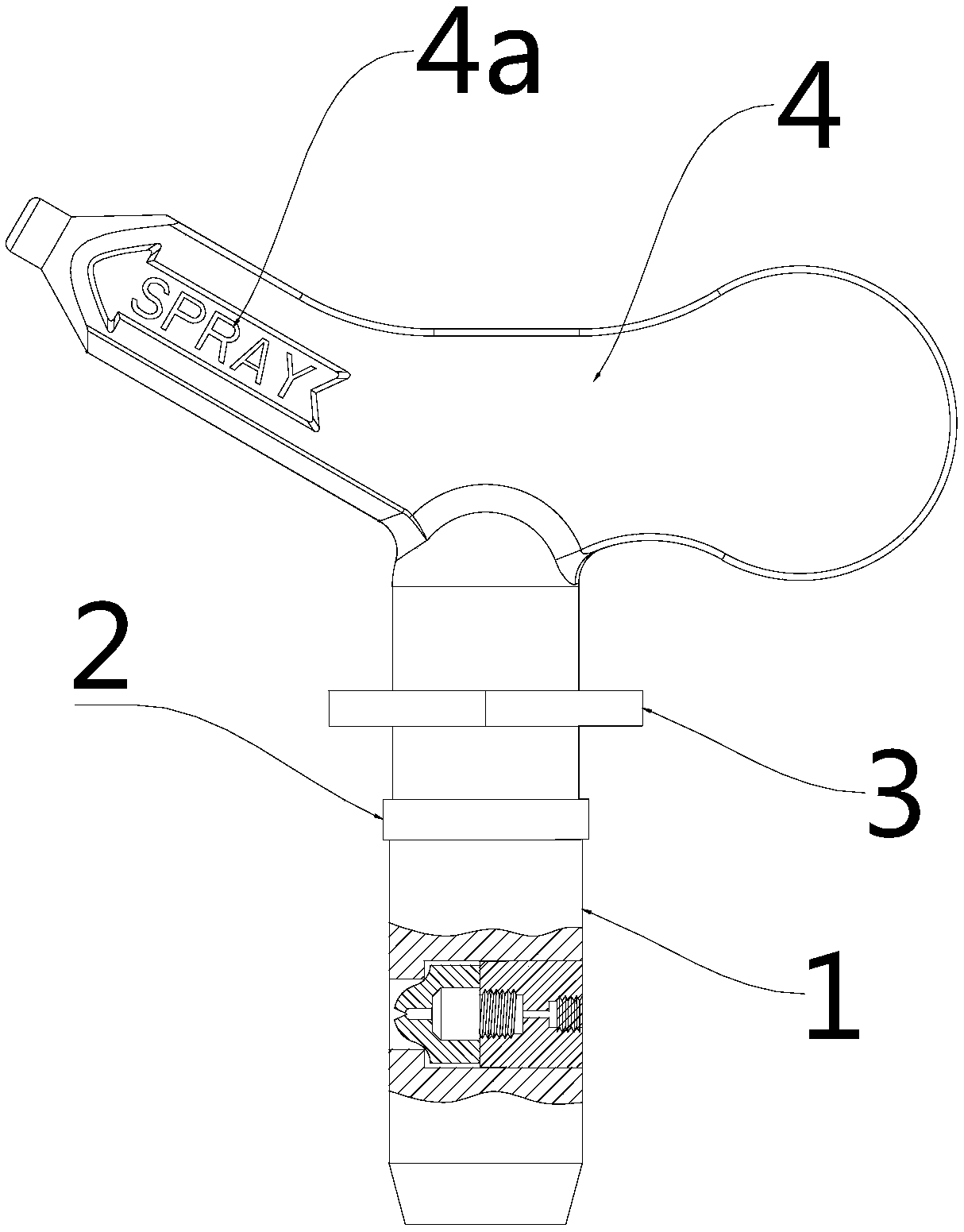
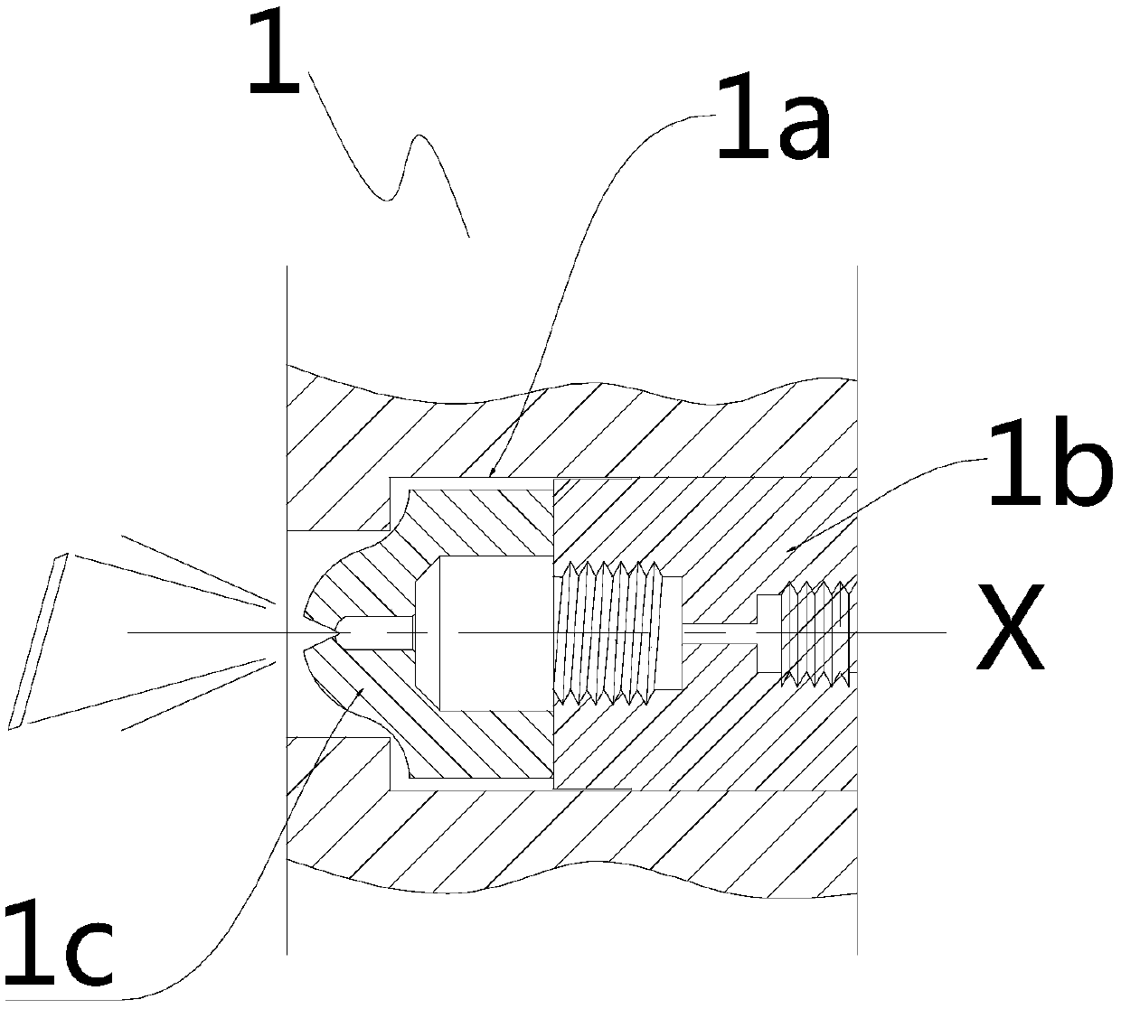
[0046] Such as Figure 2 to Figure 5 As shown, a low-pressure nozzle includes a nozzle body 1, which is made of stainless steel as a whole. There is an installation hole 1a in the middle of the nozzle body 1 along the X direction, and the installation holes 1a are installed sequentially along the X direction in the feeding direction. There are interconnected pre-atomization parts 1b and tip atomization parts 1c. The pre-atomization part 1b is opened along the X direction with a sequentially connected feed channel 1b1, pre-atomization channel 1b2 and pre-atomization pressure stabilization channel 1b3. , the feed channel 1b1, the pre-atomization channel 1b2 and the pre-atomization pressure stabilization channel 1b3 have a dumbbell-shaped structure as a whole, and the tip atomiz...


PUM


Abstract

The invention relates to a low-pressure nozzle, comprising a nozzle body, an installation hole is formed in the middle of the nozzle body along a X direction; a pre-atomizing component and a tip atomizing component which communicate with each other are sequentially installed along the feeding direction of the X direction in the installation hole; a feeding channel, a pre-atomizing channel and a pre-atomizing pressure stabilizing channel which communicate with each other are sequentially arranged in the pre-atomizing component along the X direction; the feeding channel, the pre-atomizing channel and the pre-atomizing pressure stabilizing channel are integrally dumbbell structures; a turbulence chamber, an outlet channel and an outlet orifice which communicate with each other sequentially are arranged in the tip atomizing component along the X direction; the turbulence chamber communicates with the pre-atomizing pressure stabilizing channel; and the outlet orifice has a grinded jet angle. The invention has the following advantages: when spraying at low pressure, a spraying pattern is uniformly diffused so as to eliminate stripes formed by a spraying fluid depositing at the edge or around place; whether spraying with an electric spray gun or an airless spraying machine, the spraying fluid can be uniformly coated on the surface of a workpiece without obvious stripe junction, so thecoating effect is greatly improved.

Description

technical field [0001] The invention relates to the technical field of fluid spraying, in particular to a low-pressure nozzle. Background technique [0002] Hand-held sprayers are mainly used in home painting, including hand-held electric spray guns, high-pressure airless sprayers, and general pressure hand-held spray guns. In household painting, the general spraying area is relatively small, and the working pressure of the equipment design is low, usually only one-third of the pressure of the high-pressure airless sprayer or even lower. The current trend is to use hand-held electric spray guns for concentrated and efficient small-area spraying. In this case, the sprayed pattern may have the problem of uneven diffusion. Because the input pressure of the equipment is small, more spraying fluid is deposited at or near the edge of the spraying pattern, resulting in obvious stripes on the edge of the pattern, and the distribution of the paint is uneven. Industrial coating is m...

Claims


Application Information

Patent Timeline
IPC IPC(8): B05B1/34B05B15/63
CPCB05B1/341B05B15/63B05B15/534B05B7/0012B05B1/042B05B3/087B05B7/025B05B1/046
Inventor 李碧君
Owner WUXI JINHEDA PRECISION MFG CO LTD
Why Eureka
Eureka Blog
Learn More