
Magnetic sphere body milling and meridian and latitude carving processing method

A processing method and technology of warp and latitude lines, which are applied in metal processing equipment, milling machine equipment, manufacturing tools, etc., can solve the problems of inability to complete high-precision warp and weft line engraving processing, etc., and achieve low processing cost, consistent depth and beautiful appearance, and low price Effect

Active Publication Date: 2019-04-02
INST OF OPTICS & ELECTRONICS - CHINESE ACAD OF SCI
View PDF8 Cites 0 Cited by
  • Summary
  • Abstract
  • Description
  • Claims
  • Application Information

AI Technical Summary

Problems solved by technology

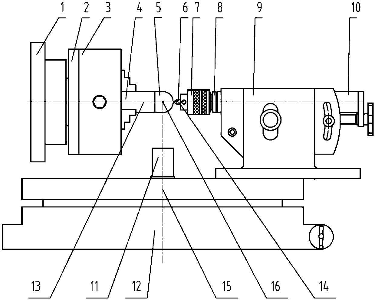
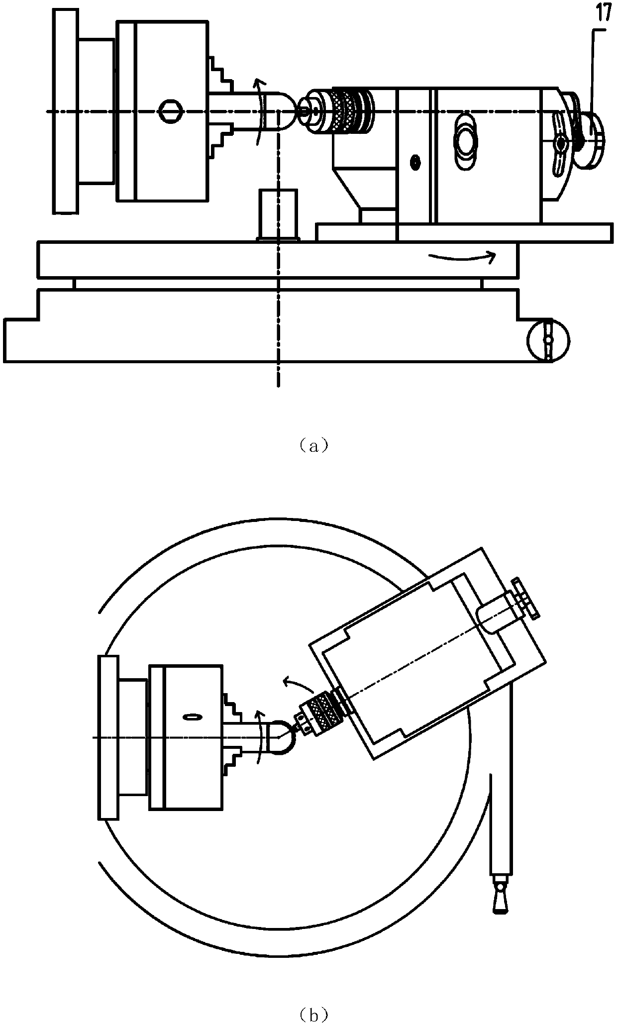
[0005] The technical problem to be solved by the present invention is: improving the existing method of processing magnetic balls can only complete the processing of magnetic balls, but cannot complete the engraving processing of high-precision latitude and longitude lines. The problem lies in: in the processing of magnetic ball spheres and sphere latitude and longitude lines It is necessary to use the same clamping state to complete the two kinds of processing; two relatively independent rotational movements are required to realize the forming of the magnetic ball sphere and the engraving processing of the longitude and latitude lines of the sphere; these two rotational movements are required to have the function of angular indexing, Realize the degree of angular indexing of longitude and latitude; in the process of engraving the longitude and latitude of the sphere, the forming rotary motion axis of the sphere longitude and latitude, the indexing rotary motion axis of the sphere longitude and latitude, and the axis of the cutter body intersect at the center of the sphere

Method used


Image

  • Magnetic sphere body milling and meridian and latitude carving processing method
  • Magnetic sphere body milling and meridian and latitude carving processing method
  • Magnetic sphere body milling and meridian and latitude carving processing method

Examples


Embodiment Construction

[0028] The present invention will be further described below in conjunction with the accompanying drawings and specific embodiments.

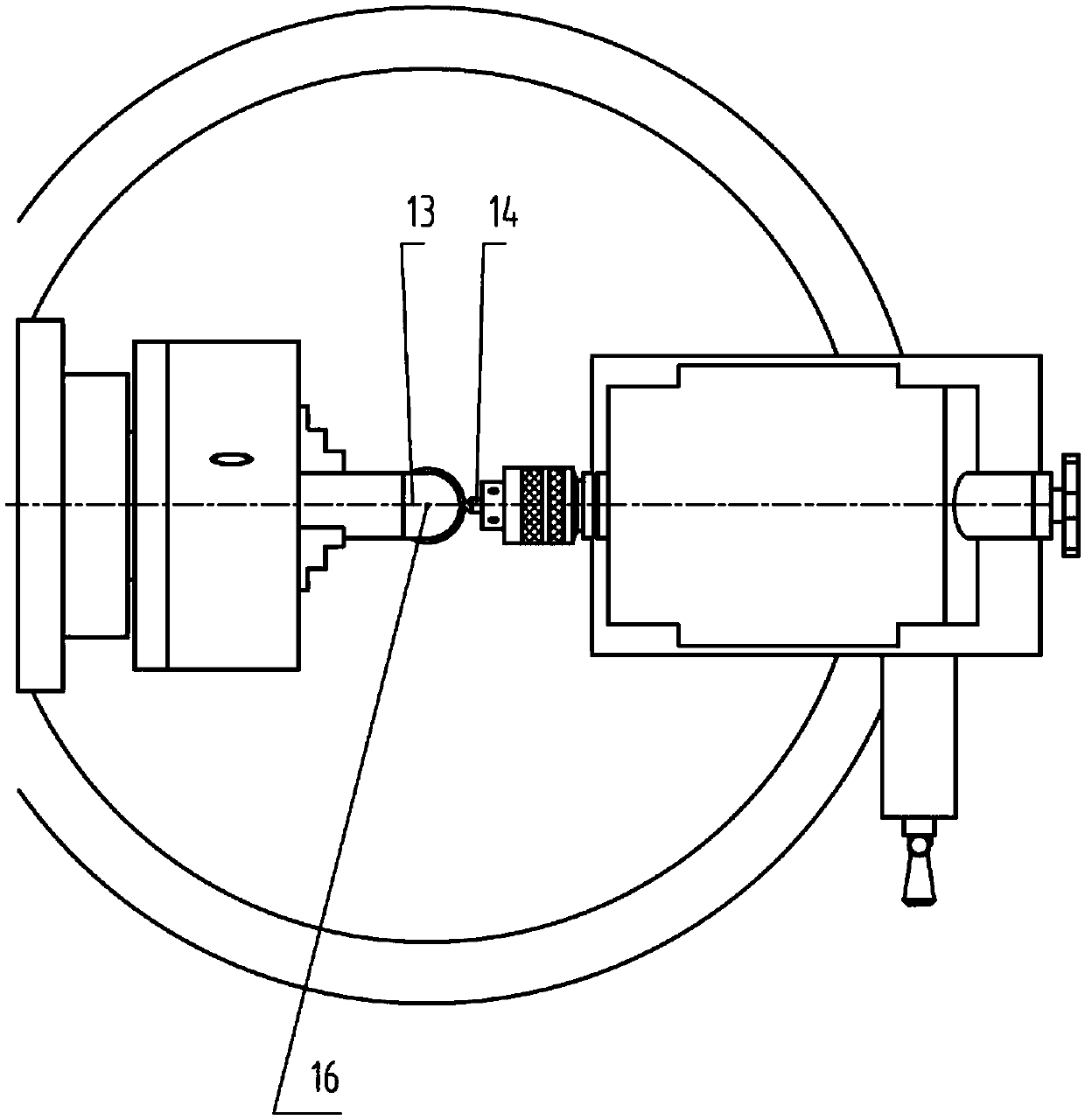
[0029] The processing equipment involved in the present invention: milling machine (universal milling machine X8130), intermediate sleeve 2 with angular index scale, three-jaw chuck 3, thread clamp 4, magnetic ball 5, cutter 6, drill chuck 7, intermediate sleeve 8, Tailstock 9, centering shaft 11, rotary table 12. The tailstock 9 is fixedly connected to the rotary table 12 on top, the intermediate sleeve 8 is installed on the tailstock 9, the drill chuck 7 is installed on the intermediate sleeve 8, the drill chuck 7 clamps the tool 6, and the intermediate sleeve with angular graduation scale 2 is installed on the spindle 1 of the milling machine, the three-jaw chuck 3 is fixedly connected with the middle sleeve 2 with an angular index scale, the three-jaw chuck 3 clamps the threaded fixture 4, and the magnetic ball 5 is screwed on the threaded ...


PUM

PropertyMeasurementUnit
depthaaaaaaaaaa

Abstract

The invention discloses a magnetic sphere body milling and meridian and latitude carving processing method. The magnetic sphere body milling and meridian and latitude carving processing method is suitable for a general tool milling machine to process polymethyl methacrylate magnetic sphere bodies and meridians and latitudes on the surfaces of the sphere bodies. The magnetic sphere body milling andmeridian and latitude carving processing method comprises the steps that a tailstock is fixed on a rotary worktable, a cutter is installed through a drill chuck by means of a middle sleeve, magneticspheres are installed on a milling machine spindle through the middle sleeve with angular indexing scales, a three-jaw chuck and a thread clamp, and rotary motion of the milling machine and the rotaryworktable are used for achieving rotary motion. Two rotation motions simultaneously processing of the magnetic spheres, as for the two rotation motions with the angular indexing function, one freedomdegree is fixed, and one rotation motion achieves meridian and latitude carving processing. Adopted equipment is simple, the processing precision is high, the carving width and depth are uniform, andappearance is beautiful.

Description

technical field [0001] The invention belongs to the technical field of mechanical manufacturing, and in particular relates to a milling method of a magnetic ball and a processing method of engraved lines of latitude and longitude. Background technique [0002] Magnetic balls are mainly used in geological exploration and detection of reservoirs and dams, and have a wide range of applications. Its material adopts organic glass material with light weight and high transparency. The shape of the magnetic ball is a hemisphere formed by processing. The surface of the hemisphere needs to be engraved with latitude and longitude lines for detection. The center of the latitude and longitude lines is required to coincide with the center of the magnetic ball. [0003] For the processing of magnetic spheres, the traditional processing methods of magnetic spheres are: (1) turning the sphere; (2) installing the processing tool on the spindle of the milling machine, and using the two rotati...

Claims


Application Information

Patent Timeline
Patent Type & Authority Applications(China)
IPC IPC(8): B23C3/02
CPCB23C3/026
Inventor 董日清王永强余伦刘会静
Owner INST OF OPTICS & ELECTRONICS - CHINESE ACAD OF SCI
Learn More