Feeding mechanism of roller pair cutting machine

A technology of feeding mechanism and cutting mechanism, which is applied in shearing device, shearing machine equipment, metal processing and other directions, can solve the problems of reduced product quality rate, material indentation, complicated adjustment mechanism, etc., and achieves improved product quality rate and stable feeding. , to avoid the effect of indentation wear

Inactive Publication Date: 2019-04-02
YANCHENG HUASEN MACHINERY
View PDF0 Cites 12 Cited by
  • Summary
  • Abstract
  • Description
  • Claims
  • Application Information

AI Technical Summary

Problems solved by technology

[0002] When the material of the cutting machine is working, it is necessary to cut the material of different thickness, but in the prior art, the feeding mechanism of the cutting machine cannot be adjusted according to the different thickness of the material, so that the cutting machine can only cut the products of the same thickness , or the adjustment mechanism is complex, so that when feeding, the material will be indented, which will lead to a decrease in the product yield. Therefore, it is necessary to design a feeding mechanism for the roller cutting machine

Method used


Image

  • Feeding mechanism of roller pair cutting machine
  • Feeding mechanism of roller pair cutting machine
  • Feeding mechanism of roller pair cutting machine

Examples


Embodiment Construction

[0018] The following will clearly and completely describe the technical solutions in the embodiments of the present invention with reference to the accompanying drawings in the embodiments of the present invention. Obviously, the described embodiments are only some, not all, embodiments of the present invention. Based on the embodiments of the present invention, all other embodiments obtained by persons of ordinary skill in the art without making creative efforts belong to the protection scope of the present invention.

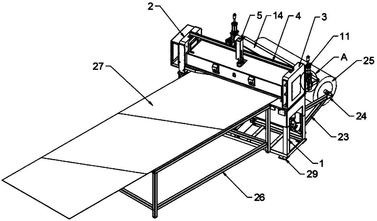
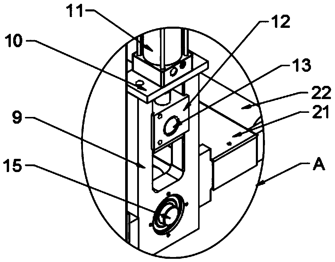
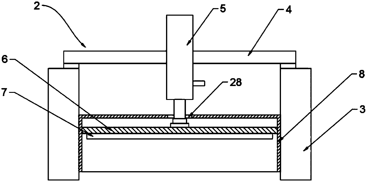
[0019] see Figure 1-4 , the present invention provides a technical solution: a feeding mechanism for a roller cutting machine, including a frame 1, a cutting mechanism 2, a U-shaped frame 9, a top plate 10, a second cylinder 11, a slider 12, a first rotating shaft 13, an upper Guide roller 14, second rotating shaft 15, lower guide roller 16, driven wheel 17, belt 18, driving wheel 19, motor 20, transition plate 21, spring drum 22, discharge rack 23, supportin...


PUM


Abstract

The invention discloses a feeding mechanism of a roller pair cutting machine. The feeding mechanism of the roller pair cutting machine comprises a frame, a cutting mechanism, an U-shaped frame, a topplate, a second cylinder, a slide block, a first rotating shaft, an upper guide roller, a second rotating shaft, a lower guide roller, a driven wheel, a belt, a driving wheel, a motor, a transition plate, a spring roller, an emptying frame, a support block, an emptying roller, a bracket, a collecting table, a through hole and a fixed block; the cutting mechanism is arranged at the upper end of theframe; the cutting mechanism comprises a support base, a cross beam, a first cylinder, a mounting plate, a cutter mold and a protective cover; through extension of the second cylinder, the slide block is driven to slide on the inner wall of the U-shaped frame up and down to drive the upper guide roller to move up and down; according to the material thickness, the upper guide roller is adjusted toa proper position for coacting with the lower guide roller to press materials; and through structural arrangement, the cutting machine can adjust the pressing gap according to the material thicknessto effectively prevent indentation and wear of the materials so as to improve the product yield.

Description

technical field [0001] The invention relates to the technical field of cutting machines, in particular to a feeding mechanism of a double-roll cutting machine. Background technique [0002] When the material of the cutting machine is working, it is necessary to cut the material of different thickness, but in the prior art, the feeding mechanism of the cutting machine cannot be adjusted according to the different thickness of the material, so that the cutting machine can only cut the products of the same thickness , or the adjustment mechanism is complicated, so that when feeding, the material will be indented, which will lead to a decrease in product yield. Therefore, it is necessary to design a feeding mechanism for the roller cutting machine. Contents of the invention [0003] The object of the present invention is to provide a feeding mechanism for a double-roll cutting machine to solve the problems raised in the above-mentioned background technology. [0004] In order...

Claims


Application Information

Patent Timeline
Patent Type & Authority Applications(China)
IPC IPC(8): B23D31/00B23Q7/00
CPCB23D31/002B23Q7/00
Inventor 韦杰陈加林
Owner YANCHENG HUASEN MACHINERY
Why Eureka
Try Eureka