Long bone fracture repositioning device

A technology of reducer and long bone, applied in the field of fracture reducer, can solve the problems of difficult fracture reduction and fixation, inconvenient operation, etc., and achieve the effect of strengthening minimally invasive awareness, avoiding re-injury, and less trauma

Active Publication Date: 2013-12-18
JIANGSU GUANGJI MEDICAL TECH
View PDF6 Cites 12 Cited by
  • Summary
  • Abstract
  • Description
  • Claims
  • Application Information

AI Technical Summary

Problems solved by technology

[0007] The purpose of the present invention is to provide a long bone fracture reducer, to solve the technical problems that the traditional long bone fracture reducer is inconvenient to operate and difficult to achieve optimal fracture reduction and fixation

Method used


Image

  • Long bone fracture repositioning device
  • Long bone fracture repositioning device
  • Long bone fracture repositioning device

Examples


Embodiment 1

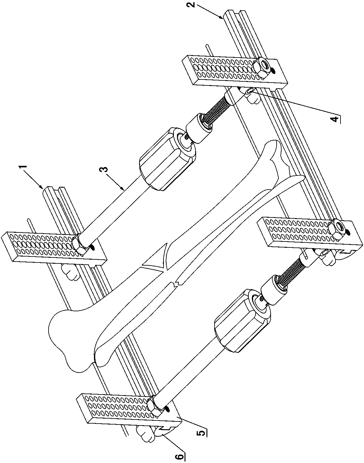
[0052] Embodiment one sees Figure 1-3 As shown, this long bone fracture reducer includes a proximal support 1, a distal support 2, a fast stretch extension rod 3 connected between the proximal support 1 and the distal support 2, and a proximal support 1 and a distal support. The steel needle fixing clip on the end support 2, and the steel needle clamped in the steel needle fixing clip.

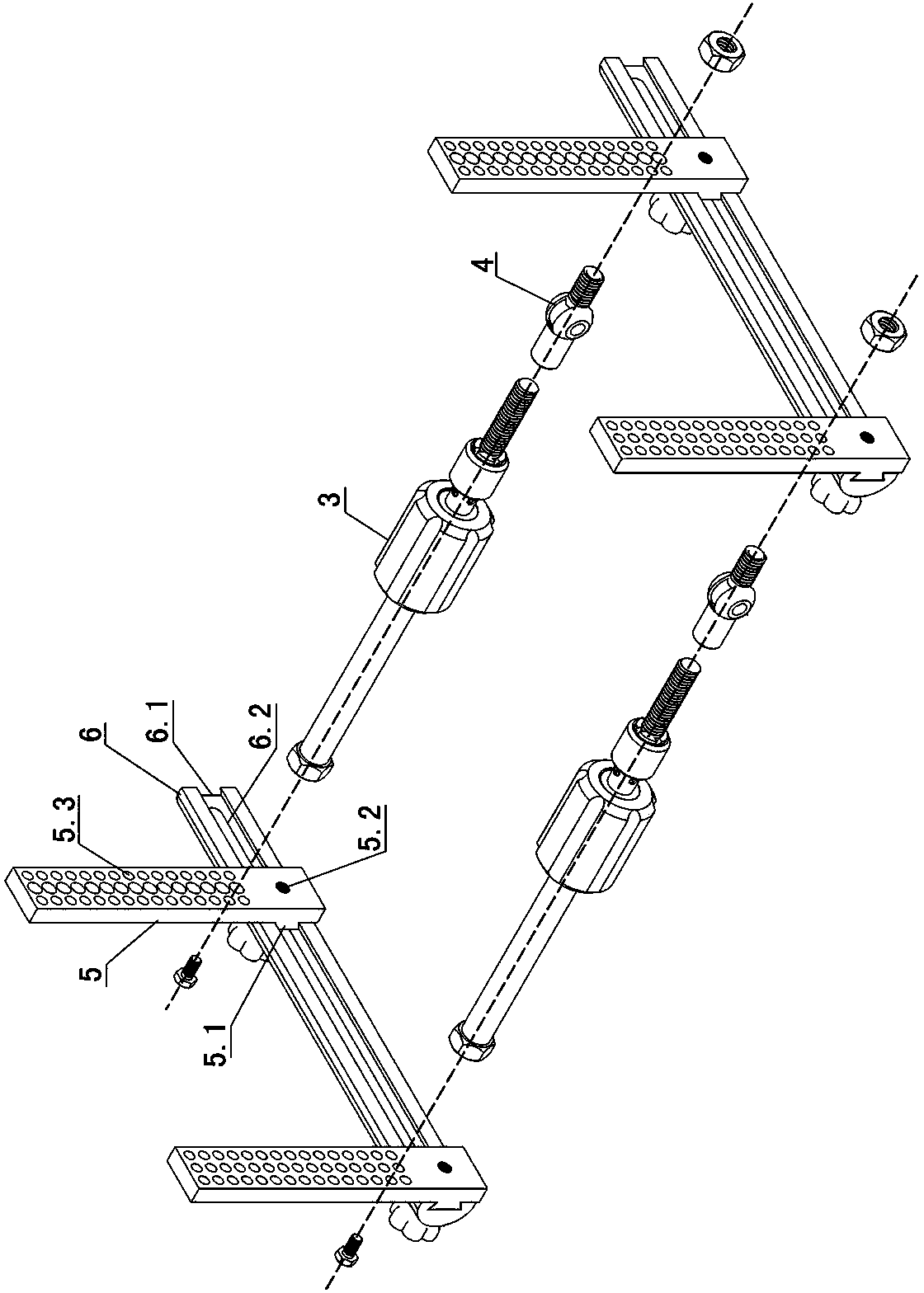
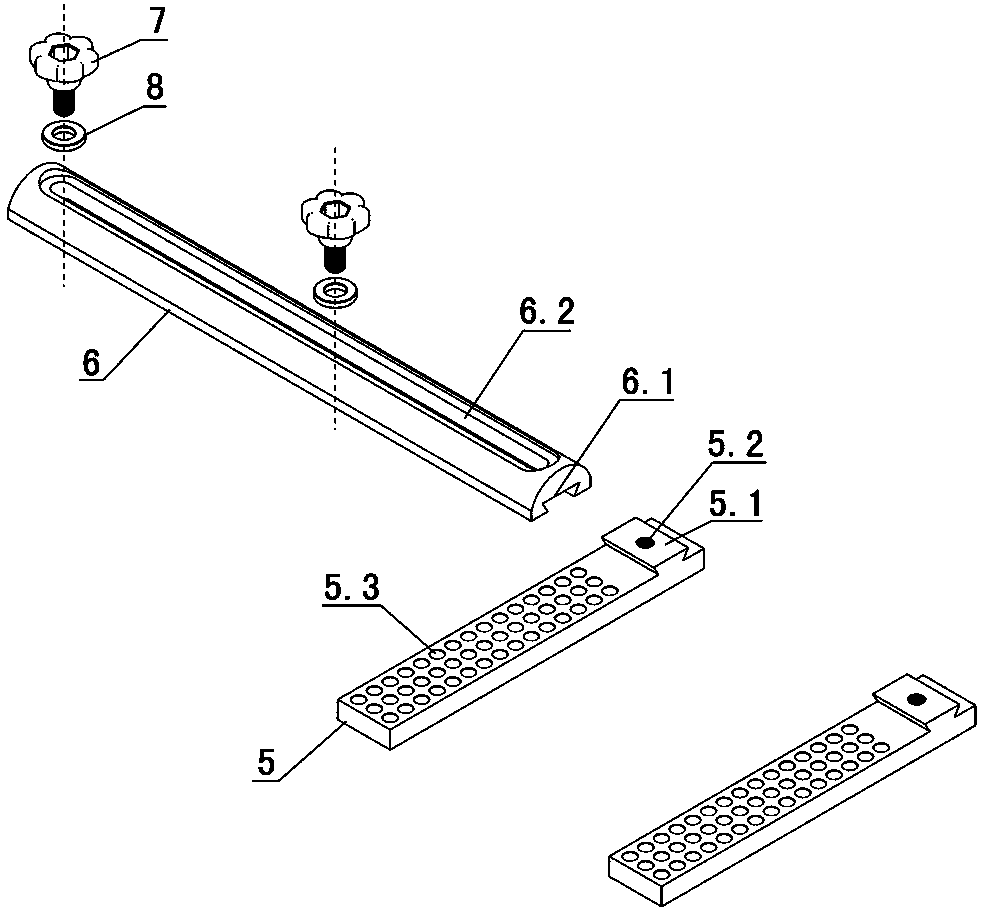
[0053] The proximal bracket 1 and the distal bracket 2 have the same structure, and both include a transverse groove-type reset slide plate 6 and two fixed sliding hole plates 5 connected to the groove-type reset slide plate 6 .

[0054] The proximal bracket 1 is also called a proximal U-shaped bow, and the distal bracket 1 is also called a distal U-shaped bow.

[0055] One side of the trough reset slide plate 6 is provided with a transverse guide chute 6.1, and a transverse guide slot 6.2 is provided between the bottom of the guide chute 6.1 and the other side of the trough reset slide plat...

Embodiment 2

[0067] Embodiment two see Figure 11-13, the second embodiment is especially suitable for the reduction of femoral fractures. The difference from the first embodiment is that one or two tubular connecting rods 10 are also connected to the fixed sliding hole plate on the proximal support 1, and the tubular connecting rods 10 Also connected with the steel needle fixing clip on the top, the steel needle clamped in the steel needle fixing clip connected to the tubular connecting rod 10 is a threaded half needle.

[0068] The tubular connecting rod 10 is connected to the fixed sliding hole plate through the tubular rod connecting piece 9 . The tubular rod connector 9 includes a lower clamp 9.1 of the tubular rod connector and an upper clamp 9.2 of the tubular rod connector, and a tubular connecting rod groove 9.3 is provided between the lower clamp 9.1 of the tubular rod connector and the upper clamp 9.2 of the tubular rod connector. The lower clamp 9.1 of the tubular rod connecto...


PUM


Abstract

The invention discloses a long bone fracture repositioning device, which comprises a proximal end support frame, a distal end support frame, quick drawing extension rods, steel needle fixing clamps and steel needles, wherein the quick drawing extension rods are connected between the proximal end support frame and the distal end support frame, the steel needle fixing clamps are connected to the proximal end support frame and the distal end support frame, the steel needles are clamped by the steel needle fixing clamps, the proximal end support frame and the distal end support frame are same in structure and respectively comprise a transverse chute type repositioning slide plate and two fixed gliding hole plates which are connected to the chute type repositioning slide plate, one surface of each chute type repositioning slide plate is provided with a transverse guide sliding chute, a transverse guide long hole is formed between the bottom of the guide sliding chute and the other surface of the chute type repositioning slide plate, the fixed gliding hole plates are provided with holes for connecting the steel needle fixing clamps, the fixed gliding hole plates are further provided with positioning bulges which are matched with the guide sliding chutes and can slide along the guide sliding chutes. The long bone fracture repositioning device disclosed by the invention is simple in structure, the minimally invasive idea is enhanced, the excellent rate of repositioning is improved, and requirements of fracture repositioning and various malformation correcting can be met to the maximum extent.

Description

technical field [0001] The invention relates to a fracture reducer, in particular to a fracture reducer for long bone fracture reduction. Background technique [0002] Fracture reduction is the basic operation of external fixation to treat fractures. With the improvement of the equipment and the improvement of the technical concept, the various adjustment functions and operating procedures of the fracture reducer have made new progress, which not only facilitates the operation, but also satisfies the requirements of fracture reduction and various deformity correction to the greatest extent. Some devices have increased fracture reduction and deformity correction functions; some have improved operating procedures, such as implementing the restoration and correction functions step by step. However, no matter how perfect the restoration function is, the external fixator is only an auxiliary tool. In most cases, it depends on the doctor's wisdom and dexterous surgery to complete...

Claims


Application Information

Patent Timeline
Patent Type & Authority Applications(China)
IPC IPC(8): A61B17/66A61B17/58
Inventor 夏和桃李刚唐佩福彭爱民杨华清夏洪菁
Owner JIANGSU GUANGJI MEDICAL TECH
Why Eureka
Try Eureka