Connecting-rod-type pipe bending and cutting integrated device

A connecting rod type and pipe material technology, applied in other manufacturing equipment/tools, manufacturing tools, etc., can solve problems such as unfavorable efficiency and increased processing time

Pending Publication Date: 2019-04-02
HUNAN UNIV OF SCI & ENG
View PDF0 Cites 19 Cited by
  • Summary
  • Abstract
  • Description
  • Claims
  • Application Information

AI Technical Summary

Problems solved by technology

[0004] However, for steel pipes that are bent by a pipe bender, they need to be cut by a cutting machine before they can be formed. Bending and cutting are two independent processes, which will inevitably increase the processing time for mass production, which is not conducive to improving efficiency.

Method used


Image

  • Connecting-rod-type pipe bending and cutting integrated device
  • Connecting-rod-type pipe bending and cutting integrated device
  • Connecting-rod-type pipe bending and cutting integrated device

Examples


Embodiment 1

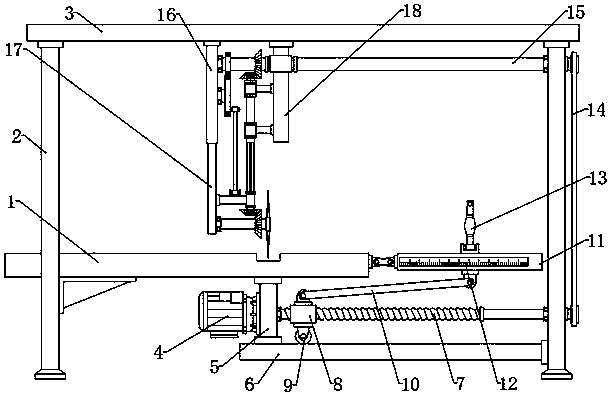
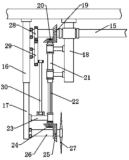
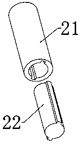
[0025] see Figure 1~4 , in an embodiment of the present invention, a connecting rod type pipe bending and cutting integrated device, including a workbench 1, a top plate 3, a screw rod 7, a movable plate 11, a sleeve 21 and a cutting knife 27; the two sides below the top plate 3 Support rods 2 are respectively fixed, wherein the lower part of one side of the support rod 2 is fixed to the workbench 1 by reinforcing ribs, the upper end of one side of the bottom plate 6 is fixed by the connection plate 5 under the workbench 1, and the other side of the bottom plate 6 is fixed on the other side of the support rod 2 The lower part, and the flange on the connecting plate 5 is equipped with a drive motor 4. Further, the drive motor 4 is connected to the power supply and the switch, and the drive motor 4 is controlled by the switch to work when the power is turned on. The connection strength of 1 improves the overall stability; the output end of the drive motor 4 is connected with a ...

Embodiment 2

[0029] In order to further explain the above-mentioned connecting rod type pipe bending and cutting integrated device, this application provides another embodiment. The connecting rod type pipe bending and cutting integrated device in this embodiment has the following technical features: the movable plate 11 A scale 12 is fixed for measuring the length of the bending part of the pipe. The middle part above the movable plate 11 is hinged at the end of the insert 13. The other end of the insert 13 is connected to the movable plate 11 by bolts. The middle part of the insert is curved in a circular arc shape. The arc-shaped insert 13 facilitates clamping and fixing of pipes with different diameters, the rotating movable plate 11 drives the bending of the steel pipe, and the scale 12 can be used to control the length of the bending part according to actual production needs.

[0030] According to the specific description of the above-mentioned embodiment, it is easy to know that the ...


PUM


Abstract

The invention discloses a connecting-rod-type pipe bending and cutting integrated device, and relates to equipment capable of synchronously bending and cutting a steel pipe. According to the connecting-rod-type pipe bending and cutting integrated device, a screw rod is brought by a motor to rotate, and then a threaded sleeve block is driven to move; a first connecting rod is brought by the threaded sleeve block to drive a moving plate to rotate and bend the steel pipe; meanwhile, a driven shaft is driven by the rotating screw rod through a synchronous belt to rotate; a small gear is driven bythe driven shaft to rotate when a first bevel gear is driven by the driven shaft to rotate; a second bevel gear and a sleeve are brought by the first bevel gear to rotate, and then a stepped shaft anda third bevel gear are brought to rotate; a fourth bevel gear, a rotating shaft and a cutting knife are brought by the third bevel gear to rotate; a large gear is brought by the small gear to drive asecond connecting rod to bring a baffle plate, the rotating shaft and the cutting knife to move up and down in a reciprocating manner; and consequently, the cutting operation on the steel pipe can beachieved.

Description

technical field [0001] The invention relates to a mechanical processing equipment, in particular to a connecting rod type pipe bending and cutting integrated device. Background technique [0002] Bending pipes are very common in production and life. No matter what kind of machinery and equipment and pipelines, most of them use bending pipes. Bending pipes are mainly used for oil, gas, liquid infusion, engineering bridge construction, etc. [0003] At present, pipe bending machines are mostly used in the production process of pipe bending. Pipe bending machines can be roughly divided into numerical control pipe bending machines, hydraulic pipe bending machines and so on. The hydraulic pipe bending machine is mainly used in electric power construction, highway and railway construction, boiler, bridge, ship, furniture, decoration and other aspects of pipeline laying and repairing. [0004] However, for steel pipes that are bent by a pipe bender, they need to be cut by a cuttin...

Claims


Application Information

Patent Timeline
Patent Type & Authority Applications(China)
IPC IPC(8): B23P23/04
CPCB23P23/04
Inventor 万李唐鑫凌刘志壮王飞
Owner HUNAN UNIV OF SCI & ENG
Why Eureka
Try Eureka