Valves and Pneumatic Braking Equipment

A technology for moving and switching elements, applied in the direction of control valves and air release valves, brakes, brake components, etc.

Active Publication Date: 2022-07-26
WABCO GMBH
View PDF13 Cites 0 Cited by
  • Summary
  • Abstract
  • Description
  • Claims
  • Application Information

AI Technical Summary

Problems solved by technology

The disadvantage is that at least the power supply

Method used


Image

  • Valves and Pneumatic Braking Equipment
  • Valves and Pneumatic Braking Equipment
  • Valves and Pneumatic Braking Equipment

Examples


Embodiment Construction

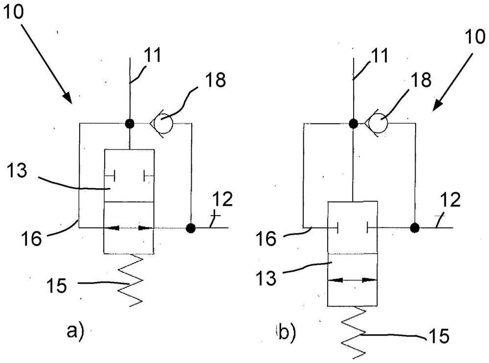
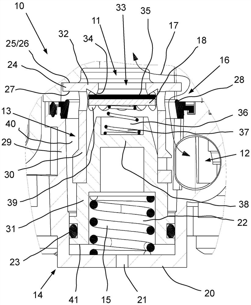
[0026] The valve 10 with the pressure input 11 and the pressure output 12 has a blocking function and a non-return function. The valve 10 is designed here as a 2 / 2-way valve.

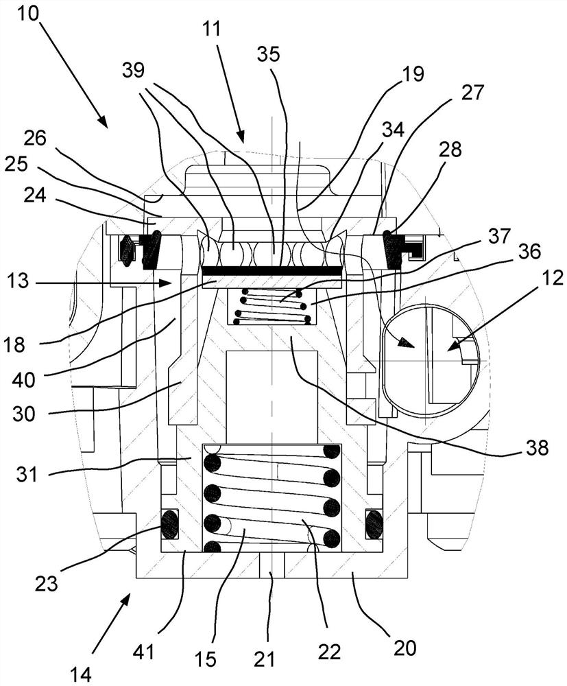
[0027] The blocking function is obtained by the positioning of the piston-like switching element 13 in the cylindrical housing 14 and cooperates with a compression spring as the restoring element 15 . As long as only a small amount of pressure is exerted on the pressure input 11 , the force of the reset element 15 prevails and the switching element 13 is positioned according to figure 1 in the conduction position of part a. Here, the pressure input 11 and the pressure output 12 are connected to each other via a bypass 16 , see also figure 2 , which has an air flow 17 through the bypass 16 shown here.

[0028] at the switching element 13 according to figure 1 By-pass 16 is closed when part b of is in the blocking position. This state can be achieved when the pressure at the pressure input 11 overco...


PUM


Abstract

The invention relates to a valve and a pneumatic braking device for pneumatic applications in vehicles, the valve comprising a pressure input (11), a pressure output (12), a switching element (13) and a reset element (15) ), wherein the switching element ( 13 ) is movable between a blocking position and a conducting position, wherein the transition from the conducting position to the blocking position is dependent on the pressure at the pressure input and the reaction of the reset element ( 15 ) force, and wherein the non-return element (18) is integrated into the switching element (13). According to the invention, the non-return element (18) can release the passage in the direction from the pressure input (11) to the pressure output (12) when the switching element (13) is in the blocking position.

Description

technical field [0001] The invention relates to a valve for pneumatic applications in vehicles, which valve has a pressure input, a pressure output, a switching element and a reset element, wherein the switching element is movable between a blocking position and a conducting position, In this case, the transition from the conducting position to the blocking position is dependent on the pressure at the pressure input and the reaction force of the reset element, and in which the non-return element is integrated into the switching element. Furthermore, the invention relates to a pneumatic braking device having such a valve. Background technique [0002] Block and check valves are well known from a variety of different pneumatic and hydraulic applications. These valves can be combined with each other to meet specific functional requirements. However, this combination of valves is disadvantageous in terms of cost and space requirements in the case of large batch sizes. [0003...

Claims


Application Information

Patent Timeline
Patent Type & Authority Patents(China)
IPC IPC(8): B60T15/02
CPCB60T15/02B60T15/18B60T15/36B60T15/42B60T17/04
Inventor 乌韦·赫尔姆斯多尔夫阿明·西克尔阿尔内·斯特凡
Owner WABCO GMBH
Why Eureka
Try Eureka