Energy-saving water pump motor

A technology of water pump motor and water chamber, which is applied in the direction of pumps, pump devices, pump components, etc., can solve the problems that the output mechanical power cannot be fully utilized, the power factor and efficiency are not high, and the unfavorable electric energy of users and the grid can be reduced. The effect of overloading electricity, saving power resources, and protecting safety

Active Publication Date: 2019-04-02
PANZHIHUA XINHUA ENERGY SAVING TECH SERVICECO
View PDF6 Cites 0 Cited by
  • Summary
  • Abstract
  • Description
  • Claims
  • Application Information

AI Technical Summary

Problems solved by technology

[0004] The water pump motor is a device that relies on the fan blades of the motor to extract water or other fluid objects. In the prior art, when liquids of different densities are extracted with the same power pump, when the solution with a high viscosity is extracted, The power of the motor will be too small, and the phenomenon of "small horses and big carts" will appear, causing the motor to be overloaded for a long time. On the one hand, it will not only consume electricity, the extraction effect will not be good, on the other hand, it will damage the insulation due to heat. cause the motor to burn out,
[0005] The same power is used to pump water for liquids with low viscosity. At this time, the power of the motor will be too large, and the phenomenon of "big horse and small cart" will appear. The output mechanical power cannot be fully utilized, and the power factor and efficiency are not high. , which is not only unfavorable to users and the power grid, but also causes waste of electric energy

Method used


Image

  • Energy-saving water pump motor
  • Energy-saving water pump motor

Examples


Embodiment Construction

[0027] In order to make the object, technical solution and advantages of the present invention clearer, the present invention will be further described in detail below in conjunction with the accompanying drawings and embodiments. It should be understood that the specific embodiments described here are only used to explain the present invention, not to limit the present invention.

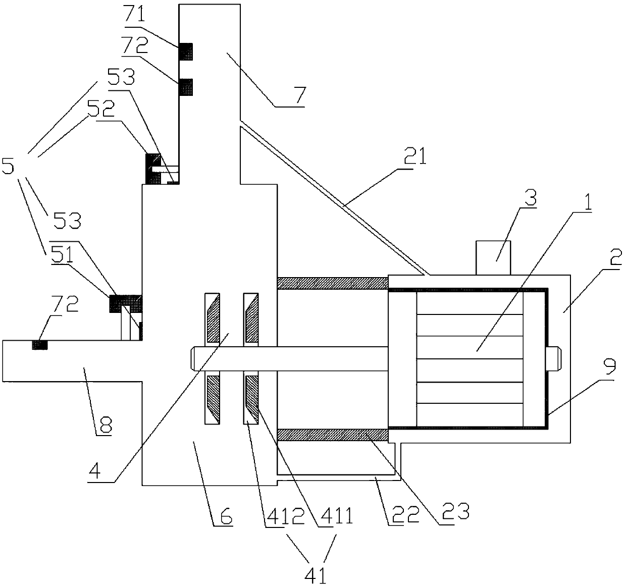
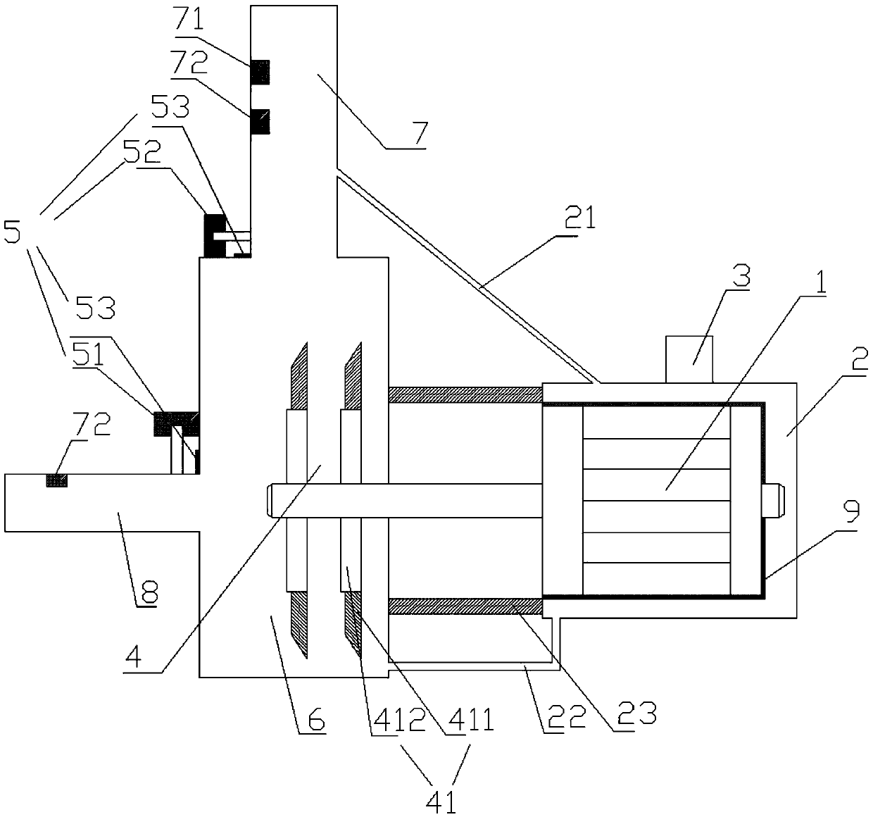
[0028] Such as Figure 1~2 As shown, an energy-saving water pump motor includes a motor 1, a liquid storage chamber 2, a controller, a rotating part 4, a pushing part 5, a water passage chamber 6, a water inlet pipe 7 and a water outlet pipe 8, and the motor 1 is arranged in the liquid storage chamber Inside the chamber 2, the outer layer of the motor 1 is provided with a layer of heat-exchanging copper 9, the heat-exchanging copper 9 is closely attached to the motor 1, and the heat-exchanging copper 9 exchanges heat with the liquid in the liquid storage chamber 2, so that the motor 1 automatically...


PUM


Abstract

The invention discloses an energy-saving water pump motor. The energy-saving water pump motor comprises a motor, a liquid storage cavity, a controller, a rotating part, a pushing part, a water passingcavity, a water inlet pipe and a water outlet pipe, wherein the motor is arranged inside the liquid storage cavity, a layer of heat exchange copper is arranged on the outer layer of the motor, and the heat exchange copper exchanges heat with liquid in the liquid storage cavity; the controller is arranged on a shell of the liquid storage cavity, the rotating part is connected with the motor in a clamping mode, and the rotating part is arranged in the water passing cavity; the rotating part is connected with the controller, and rotating fan blades of the rotating part are adjustable in length;the water passing cavity is formed in the front side position of the output end of the motor, and the water passing cavity is fixedly connected with the liquid storage cavity through a fixed shell; and the water inlet pipe and the water outlet pipe are arranged on the water passing cavity, and the pipe diameter of the water inlet pipe and the water outlet pipe can be adjusted.

Description

technical field [0001] The invention relates to the field of motor energy saving, in particular to an energy-saving water pump motor. Background technique [0002] The motor refers to the realization of electric energy according to the law of electromagnetic induction. [0003] An electromagnetic device that converts or transmits. It is represented by the letter M (D in the old standard) in the circuit. Its main function is to generate driving torque as a power source for electrical appliances or various machinery. A generator is represented by the letter G in the circuit. Its main function is to convert mechanical energy into electrical energy. At present, the most commonly used is to use heat energy, water energy, etc. to drive the rotor of the generator to generate electricity. [0004] The water pump motor is a device that relies on the fan blades of the motor to extract water or other fluid objects. In the prior art, when liquids of different densities are extracted...

Claims


Application Information

Patent Timeline
Patent Type & Authority Applications(China)
IPC IPC(8): F04D13/06F04D15/00F04D29/18F04D29/40F04D29/58
CPCF04D13/0653F04D15/0022F04D15/0055F04D29/18F04D29/406F04D29/5806F04D29/5893F05D2270/65
Inventor 许成明
Owner PANZHIHUA XINHUA ENERGY SAVING TECH SERVICECO
Why Eureka
Try Eureka