
Detection device for on-off fault of power system optical fiber

A technology for on-off and fault detection of optical fiber, which is applied in the direction of measuring devices, optical instrument testing, and testing optical fiber/optical waveguide equipment, etc., can solve the problem of single function of the optical fiber on-off detection device, and improve resource utilization and accuracy , the effect of reducing the cost of use

Inactive Publication Date: 2019-04-02
STATE GRID GASU ELECTRIC POWER RES INST +2
View PDF1 Cites 3 Cited by
  • Summary
  • Abstract
  • Description
  • Claims
  • Application Information

AI Technical Summary

Problems solved by technology

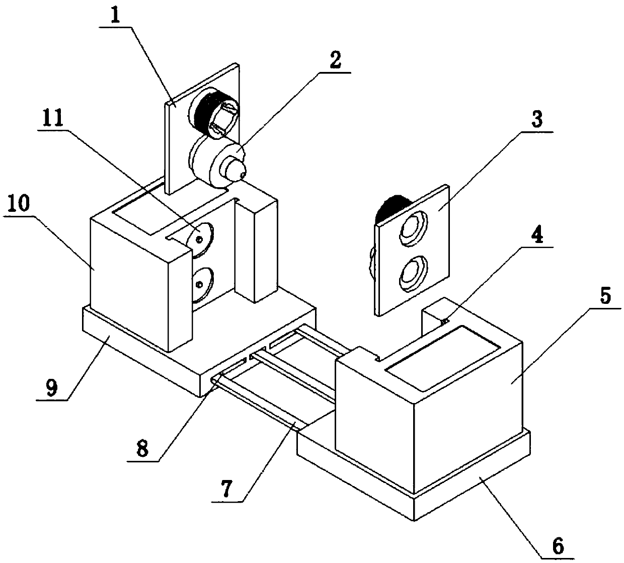
[0003] The technical problem to be solved by the present invention is to provide a power system optical fiber on-off fault detection device for the single-function problem of the existing optical fiber on-off detection device, by setting laser emitting modules on the fixed base and the movable base and the laser receiving module, and use guide rails and slide bars to connect the fixed base and the movable base, so as to prevent accidental loss. Effectively fix the position of the optical fiber, thereby improving the accuracy of the test

Method used


Image

  • Detection device for on-off fault of power system optical fiber
  • Detection device for on-off fault of power system optical fiber
  • Detection device for on-off fault of power system optical fiber

Examples


Embodiment Construction

[0023] The present invention will be described in detail below in conjunction with the accompanying drawings and specific embodiments. The exemplary embodiments and descriptions of the present invention explain the present invention, but are not intended to limit the present invention.

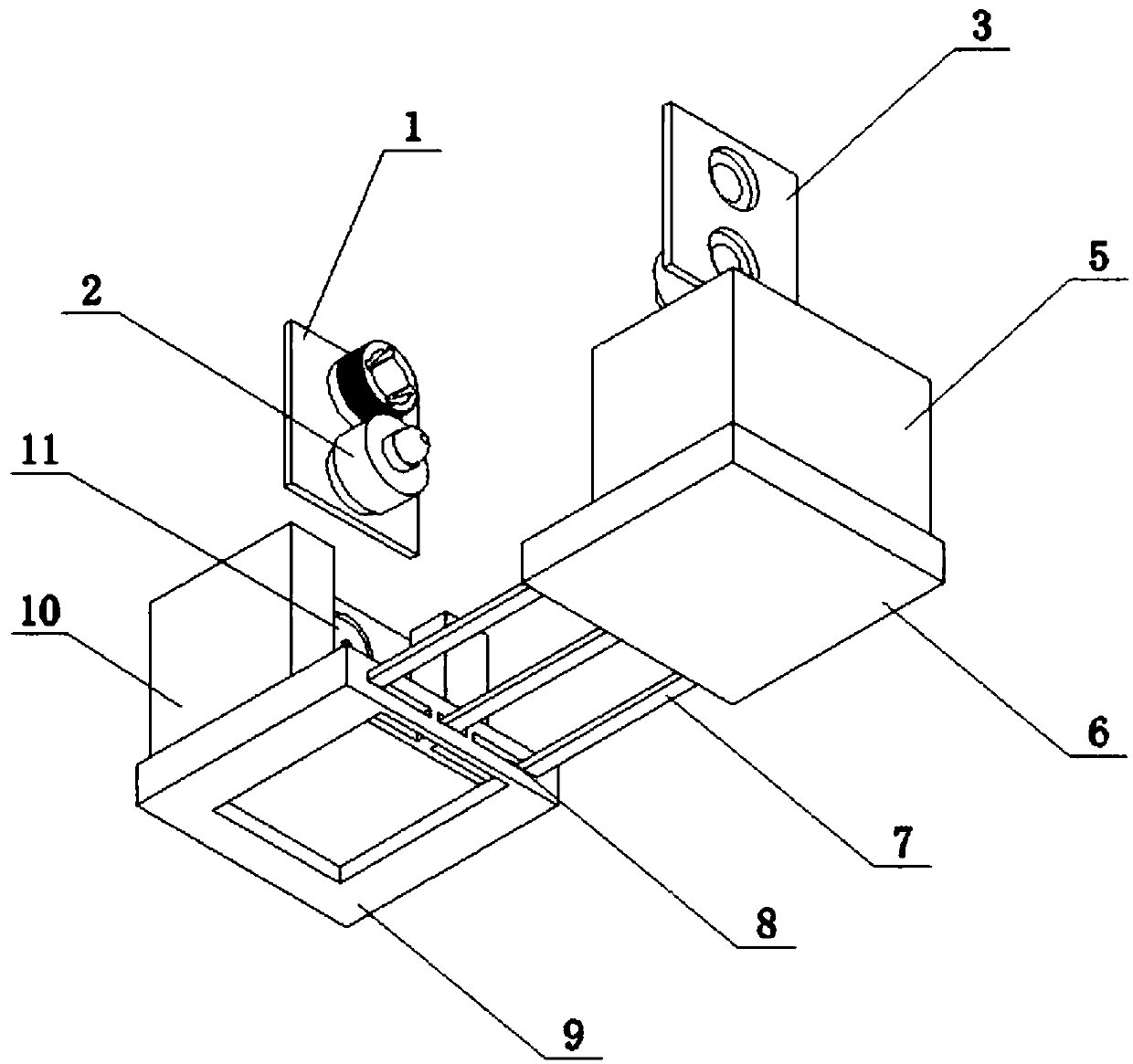
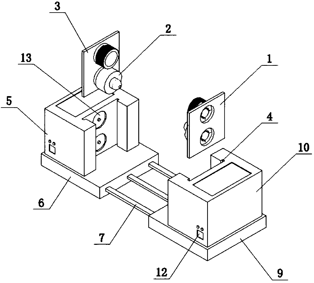
[0024] Such as Figure 1-6 As shown, a power system optical fiber on-off fault detection device according to the present invention includes a fixed base 6, the bottom of the fixed base 6 is connected to the movable base 9 through a slide bar 7, and the upper surface of the top is fixedly provided with The laser emitting module 5 is provided with a laser emitter 13 on the inner center line of the laser emitting module 5; the bottom of the movable base 9 is provided with a guide rail 8 matched with the slide bar 7, and the upper surface of the top is fixedly provided with a laser receiving module 10. A laser receiving module 10 is provided on the inner center line of the laser receiving module 1...


PUM


Abstract

The invention relates to the technical field of optical fiber on-off detection equipment, and aims to provide a detection device for on-off faults of a power system optical fiber which can effectivelysolve the problem that existing detection devices for optical fiber on-off are single in function. The device comprises a fixed base. The fixed base is connected with a movable base through a slidingrod and is provided with a laser emission module on the upper surface. A laser transmitter is arranged on the laser emission module. A laser receiving module is arranged on the upper surface of the movable base. A laser receiving module is arranged on the laser receiving module. The laser emission module and the laser receiving module are respectively connected with a laser emission limiting plate and a laser receiving limiting plate through a bayonet. A threaded pipe is arranged on both the laser emission limiting plate and the laser receiving limiting plate. The detection device for on-offfaults of the power system optical fiber has the advantages that the on-off of the optical fiber can be detected, and detection of the optical fiber break point can also be used through cooperation ofthe laser emission module, the laser receiving module, and the threaded pipe, so as to improve the resource utilization rate.

Description

technical field [0001] The invention relates to the technical field of optical fiber on-off detection equipment, in particular to a power system optical fiber on-off fault detection device. Background technique [0002] An optical fiber (optic fiber) is a fiber made of glass or plastic that acts as a means of transmitting light. The transmission principle is 'total reflection of light', and the tiny optical fiber is encapsulated in a plastic sheath, allowing it to be bent without breaking. Usually, the transmitting device at one end of the optical fiber uses a light emitting diode (LED) or a laser beam to transmit light pulses to the optical fiber, and the receiving device at the other end of the optical fiber uses a photosensitive element to detect the pulse. In daily life, optical fibers are used for long-distance information transmission because the transmission loss of light in optical fibers is much lower than that of electricity in wires. Most optical fibers are coat...

Claims


Application Information

Patent Timeline
IPC IPC(8): G01M11/00
CPCG01M11/30
Inventor 杨勇李兴德范迪龙钱康康晓华陈林顾煊汪红燕安亮亮刘诣超马玲
Owner STATE GRID GASU ELECTRIC POWER RES INST
Learn More