A multifunctional demonstration device for career planning
A demonstration device and multifunctional technology, which is applied in the field of multifunctional demonstration devices for career planning, can solve problems such as laborious swinging, limited carrying area of blackboard or whiteboard, and small cleaning area of cleaning tools
- Summary
- Abstract
- Description
- Claims
- Application Information
AI Technical Summary
Problems solved by technology
Method used
Image
Examples
Embodiment 1
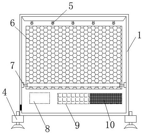
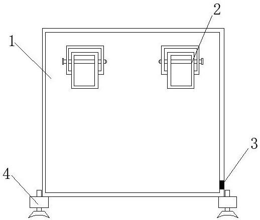
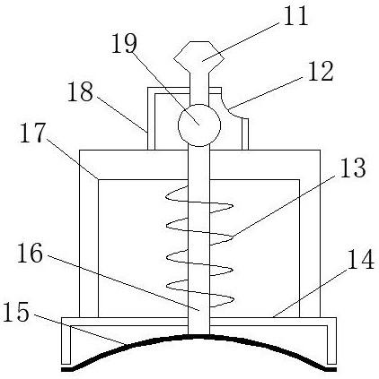
[0023] Embodiment 1: refer to Figure 1-3 , a multifunctional demonstration device for career planning, including a demonstration frame 1, a controller 8 and a battery pack 10, and also includes a stable seat 4 and a clamping device 2; the left and right sides of the bottom surface of the demonstration frame 1 are fixedly connected with stable seats 4. The lower end of the left side of the demonstration frame 1 is provided with a power interface 3, the top of the demonstration frame 1 is equidistantly provided with LED lights 5, the front of the demonstration frame 1 is provided with a writing panel 6, and the left and right sides of the upper end of the back of the demonstration frame 1 are equally spaced. A clamping device 2 is provided, a wiping device 7 is provided between the left and right frames of the demonstration frame body 1, and a controller 8, an operation panel 9 and a battery pack 10 are fixedly installed on the inner bottom of the demonstration frame body 1 from...
Embodiment 2
[0026] Embodiment 2: refer to Figure 4-5 , combined with the basis of Embodiment 1, the clamping device 2 includes a clamping frame 22, a shaft 20 and a clamping plate 27, the upper end of the clamping plate 27 is provided with a shaft cavity 28 inside, and the shaft 20 passes through the shaft cavity 28 to clamp the clamping plate 27 is rotatably connected inside the clamping frame 22, the middle section of the shaft rod 20 is provided with a threaded groove 21, the middle section inside the shaft cavity 28 is provided with threaded teeth matching the threaded groove 21, and the upper right side of the clamping frame 22 is provided with a gear groove 23. The right side of the clamping plate 27 is fixedly connected with the driven wheel 26, and the right side of the clamping frame 22 rotates from right to left through the reset rotating shaft 29 and is connected with the driving wheel 24 and the pressing rod 25. The reset rotating shaft 29 is far away from the surface of the c...
PUM
 Abstract
Description
Claims
Application Information
 - R&D
- Intellectual Property
- Life Sciences
- Materials
- Tech Scout
- Unparalleled Data Quality
- Higher Quality Content
- 60% Fewer Hallucinations
Browse by: Latest US Patents, China's latest patents, Technical Efficacy Thesaurus, Application Domain, Technology Topic, Popular Technical Reports.
© 2025 PatSnap. All rights reserved.Legal|Privacy policy|Modern Slavery Act Transparency Statement|Sitemap|About US| Contact US: help@patsnap.com


