A reflectarray antenna with low rcs characteristics

A reflect array antenna and reflect array technology, which is applied in the directions of individually powered antenna arrays, antennas, antenna arrays, etc., can solve the problems of restricting the application of reflect array antennas, unable to meet the needs of military applications, etc., achieving low cost, easy processing, good quality The effect of the application foreground

Inactive Publication Date: 2020-11-03
AIR FORCE UNIV PLA
View PDF11 Cites 0 Cited by
  • Summary
  • Abstract
  • Description
  • Claims
  • Application Information

AI Technical Summary

Problems solved by technology

[0006] It should be noted that although reflectarray antennas combine array antennas and reflector antennas, such high-gain antennas still cannot avoid large apertures, and large apertures cannot avoid large backward RCS
We know that with the stealth development of modern attack systems, this kind of antenna with a large backward RCS cannot meet the needs of military applications, which seriously restricts the application of reflectarray antennas in the military field

Method used


Image

  • A reflectarray antenna with low rcs characteristics
  • A reflectarray antenna with low rcs characteristics
  • A reflectarray antenna with low rcs characteristics

Examples


Embodiment Construction

[0027] The technical solution of the present invention will be described in further detail below in conjunction with the accompanying drawings and specific embodiments.

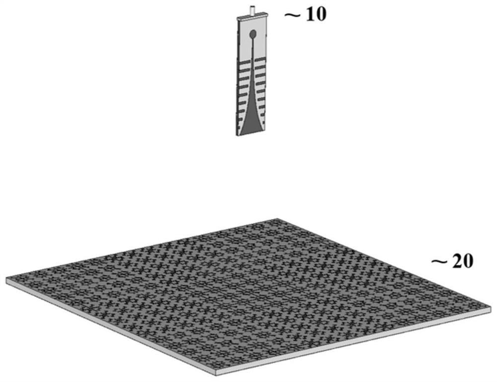
[0028] Such as figure 1 As shown, the designed low RCS reflectarray antenna consists of the Vivaldi feed shown in structure 10 and the single-layer reflectarray shown in structure 20, where the phase center of the Vivaldi antenna at 9 GHz is located at the focal point directly above the center of the single-layer reflectarray .

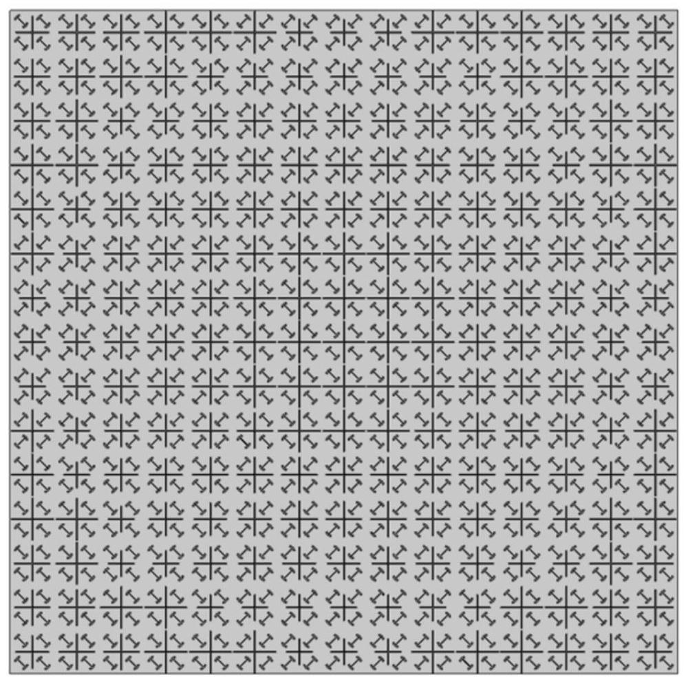
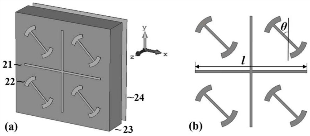
[0029] figure 2 The top view of the single-layer reflective array is given. This type of single-layer reflective array is composed of 15×15 cross-shaped structures and 30×30 “I”-shaped structures. The array size is 165×165mm 2 . It can be seen that each cross-shaped structure is inlaid in the center of four "I"-shaped structures. It can be seen that the basic units of this type of reflectarray are a cross-shaped structure and four "I"-shaped structures.

[0030] Unit structure ...


PUM


Abstract

The invention discloses a reflectarray antenna with low RCS characteristics. The reflectarray antenna is composed of a Vivaldi antenna feed source and a single-layer reflectarray; the single-layer reflectarray consists of a reflectarray working in the Ku band The antenna unit is jointly nested with the reflectarray antenna unit working in the X-band. Wherein, the single-layer reflectarray is composed of units working in the Ku-band and units working in the X-band jointly nested. The single-layer reflectarray can effectively reduce the back RCS in the Ku band to form low RCS characteristics, and can convert the spherical wave radiated by the Vivaldi feeder into a plane wave in the X band to form a high-gain radiation effect.

Description

technical field [0001] The invention belongs to the field of antennas, in particular to a reflection array antenna with low RCS characteristics. Background technique [0002] Classical high-gain antennas mainly include reflector antennas and array antennas. Reflector antennas are difficult to process, high in profile, heavy, and inconvenient to carry due to their curved structure, while array antennas can better avoid reflections due to their planar structure. However, it should be noted that array antennas often require a complex feed network, especially when the number of array elements is large, the loss of the feed network greatly limits the improvement of antenna efficiency. The reflectarray antenna combines the advantages of the array antenna and the reflector antenna. It has a planar structure and does not require a complicated feeding network. Therefore, it not only has the advantages of the above two high-gain antennas, but also avoids them. Shortcomings. Therefor...

Claims


Application Information

Patent Timeline
Patent Type & Authority Patents(China)
IPC IPC(8): H01Q1/38H01Q3/30H01Q15/14H01Q15/24H01Q21/06
CPCH01Q1/38H01Q3/30H01Q15/14H01Q15/242H01Q21/065
Inventor 郭文龙王光明高向军李海鹏刘凯越
Owner AIR FORCE UNIV PLA
Why Eureka
Try Eureka