A Planar Low Profile Microstrip Filter Antenna Based on a Bandpass Filter Prototype

A bandpass filter and microstrip filtering technology, applied in resonant antennas, waveguide devices, antenna grounding devices, etc., can solve the problems of increased processing, assembly and debugging, limited miniaturization and integration of filter antennas, and high processing costs , to achieve the effect of improving frequency selectivity, high level of out-of-band rejection, and low-profile plane design

Active Publication Date: 2021-10-08
成都频时科技有限公司
View PDF10 Cites 0 Cited by
  • Summary
  • Abstract
  • Description
  • Claims
  • Application Information

AI Technical Summary

Problems solved by technology

However, the introduction of various complex parasitic structures makes the design process of the filter antenna very complicated; the parasitic structure will also introduce parasitic modes, resulting in a low level of out-of-band suppression; Reduce the difficulty of processing, assembly and debugging
[0005] To sum up, the existing filter antenna technical solutions (1) and (2) are limited by the existence of the filter circuit, and the improvement of the designed filter antenna in terms of miniaturization and integration is very limited; the solution (3) is due to the FSS The existence of the radome has the problems of large overall volume, low antenna radiation efficiency, and high processing cost; scheme (4) has problems such as complicated filter antenna design process, low level of out-of-band suppression, and complex antenna structure.

Method used


Image

  • A Planar Low Profile Microstrip Filter Antenna Based on a Bandpass Filter Prototype
  • A Planar Low Profile Microstrip Filter Antenna Based on a Bandpass Filter Prototype
  • A Planar Low Profile Microstrip Filter Antenna Based on a Bandpass Filter Prototype

Examples


Embodiment Construction

[0056] The specific embodiments of the present invention are described below so that those skilled in the art can understand the present invention, but it should be clear that the present invention is not limited to the scope of the specific embodiments. For those of ordinary skill in the art, as long as various changes Within the spirit and scope of the present invention defined and determined by the appended claims, these changes are obvious, and all inventions and creations using the concept of the present invention are included in the protection list.

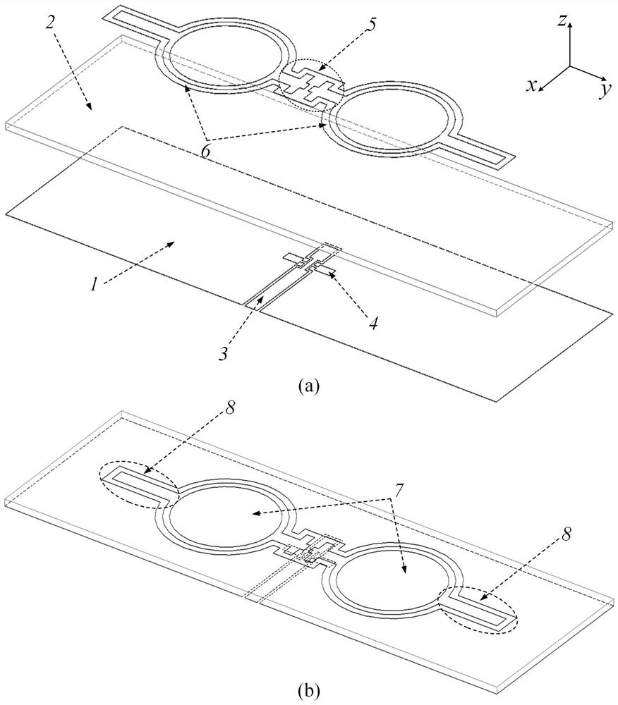
[0057] The invention provides a filtering antenna technology based on a Bandpass Filter (BPF) prototype, which can realize a radiation filtering response with a high level of out-of-band suppression without using an external filtering circuit and a complex parasitic structure. At the same time, the physical form of the proposed filter antenna is a microstrip differentially coupled line-fed double-patch radiator, and its stru...


PUM


Abstract

The invention provides a flat low-profile microstrip filter antenna based on a band-pass filter prototype, which belongs to the field of communication technology, including a dielectric substrate and a floor. The invention provides a filter antenna technology based on a band-pass filter prototype, which can be used without A radiation filter response with a high level of out-of-band rejection is achieved using an additional filter circuit and complex parasitic structures. At the same time, the physical form of the proposed filter antenna is a microstrip coupled line-fed double patch radiator, and its structure is very simple and easy to process. The coplanar waveguide-slot line-microstrip line transition structure is used as both a balun and a power divider to excite differentially coupled lines to improve frequency selectivity and out-of-band rejection by introducing hybrid electromagnetic coupling feeding techniques . The microstrip filter antenna has a low profile and a compact structure, which is beneficial to the miniaturization and integration design of the radio frequency front end.

Description

technical field [0001] The invention belongs to the technical field of filter antennas, in particular to a flat low-profile microstrip filter antenna based on a band-pass filter prototype. Background technique [0002] Antenna and filter are two important components of the RF front-end. Among them, the antenna is responsible for receiving / transmitting electromagnetic signals, and the filter is responsible for filtering interference signals. Their performance plays a decisive role in the overall working quality of the wireless communication system. In order to comply with the development trend of miniaturization and integration of wireless communication systems, filter antenna technology has been proposed and received extensive attention in recent years. Filtering antenna technology can integrate the filtering function of traditional filters and the radiation function of antennas in the same device, which can effectively reduce the size of the RF front-end, reduce loss and im...

Claims


Application Information

Patent Timeline
Patent Type & Authority Patents(China)
IPC IPC(8): H01Q1/38H01Q1/48H01Q1/50H01Q9/04H01Q9/16H01P1/203
CPCH01P1/203H01Q1/38H01Q1/48H01Q1/50H01Q9/0407H01Q9/16
Inventor 董元旦姬硕生王崭
Owner 成都频时科技有限公司
Why Eureka
Try Eureka