Low-profile circularly polarized vortex wave folded transmissive array antenna based on metasurface

A metasurface and vortex wave technology, used in wireless communication, radar, and antenna fields, can solve the problem that the antenna is difficult to meet the communication needs, and achieve the effect of miniaturization and height reduction.

Active Publication Date: 2022-04-19
XIDIAN UNIV
View PDF8 Cites 0 Cited by
  • Summary
  • Abstract
  • Description
  • Claims
  • Application Information

AI Technical Summary

Problems solved by technology

The disadvantage of the above-mentioned prior art is that the transmission array antenna can only fix the cross-sectional volume of the antenna to one-third of the focal length, and the cross-section of the antenna cannot be further reduced due to the problem of folding the optical path, but this is not the case for low-frequency transmission array antennas. , the cross-sectional volume is still large under one-third of the focal length, so it is expected to further reduce the height of the cross-section; at the same time, the transmission array antenna is only capable of realizing simple linearly polarized radiation beams, for some specific More occasions are to transmit and receive circularly polarized radiation beams, so it is also expected that the transmission array antenna has better polarization conversion capability
In addition, compared with pen beam radiation, vortex wave radiation based on orbital angular momentum, as a new communication method, can realize parallel transmission of multiple channels of information in the same frequency band, which can greatly improve spectrum utilization. In the communication environment, the pen beam radiation antenna that can only transmit a single information is difficult to meet the communication needs, so it is expected that the antenna can generate vortex wave radiation

Method used


Image

  • Low-profile circularly polarized vortex wave folded transmissive array antenna based on metasurface
  • Low-profile circularly polarized vortex wave folded transmissive array antenna based on metasurface
  • Low-profile circularly polarized vortex wave folded transmissive array antenna based on metasurface

Examples


Embodiment Construction

[0030] The present invention will be further described below in conjunction with the accompanying drawings and specific embodiments.

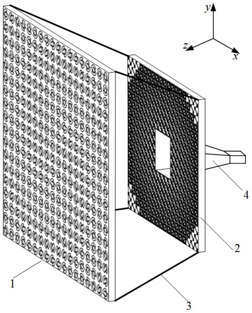
[0031] refer to figure 1 , the present invention includes a main transmission mirror 1, a secondary reflection mirror 2, a support structure 3 and a feed source 4, wherein:

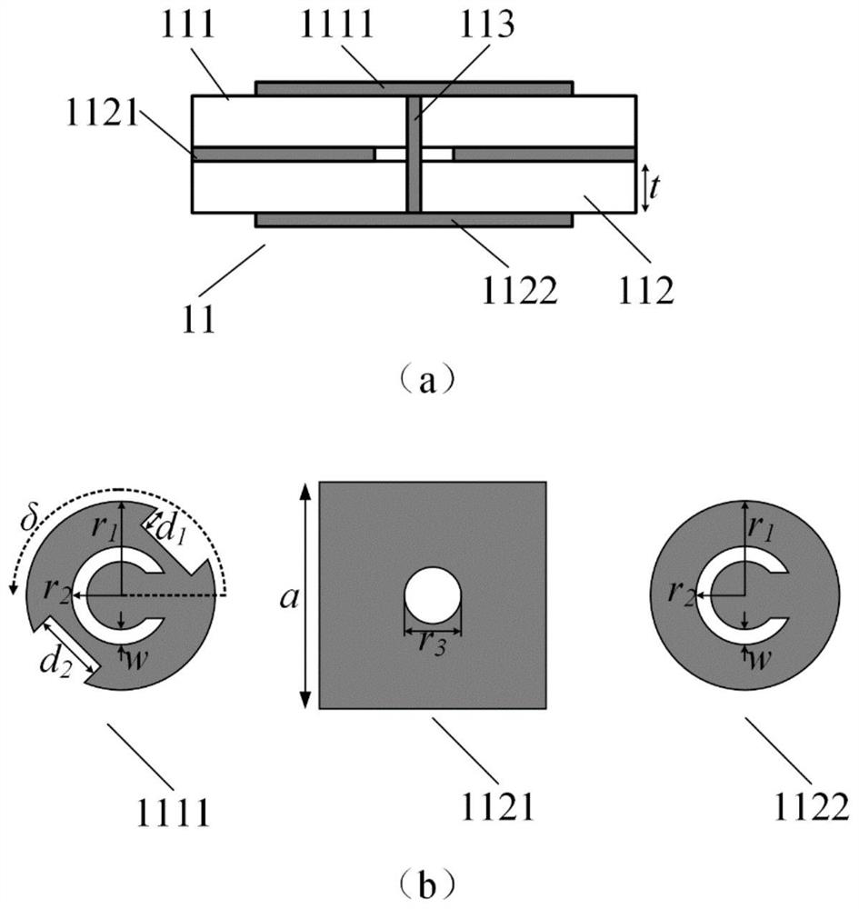
[0032] The primary transmission mirror 1 includes 26×26 periodically arranged first metasurface units 11 .

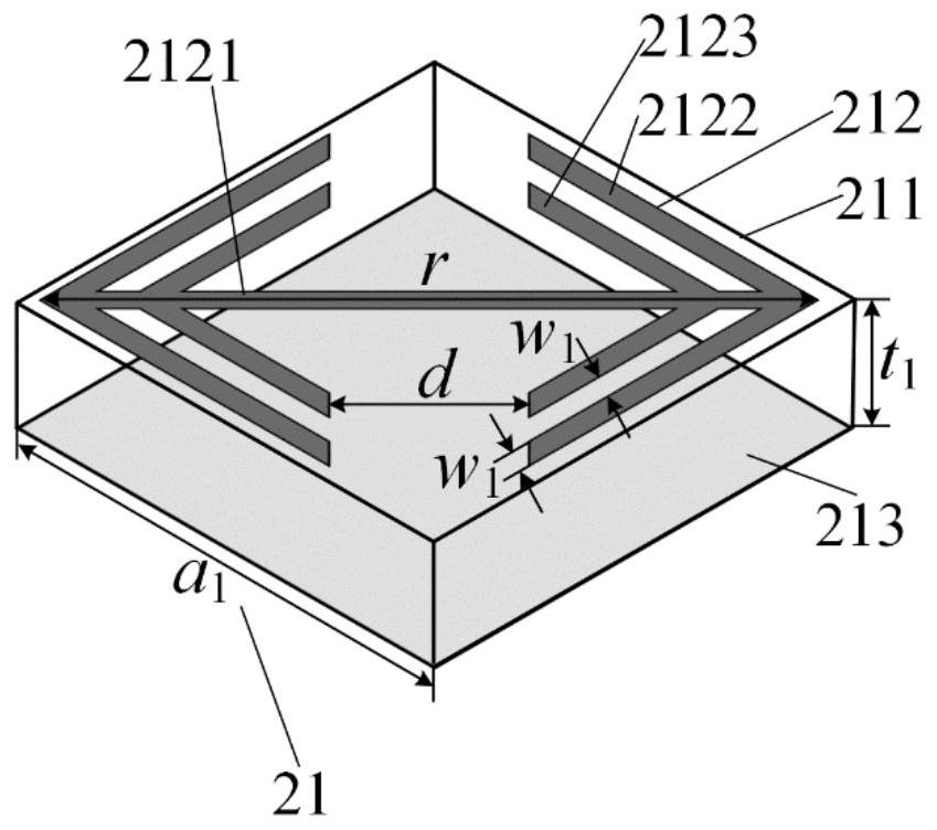
[0033] The secondary mirror 2 includes 26×26 second metasurface units 21 arranged periodically, and the center is hollowed out.

[0034] The sub-reflector 2 is fixed at the quarter focal length position of the main transmission mirror 1 by a support structure 3 of non-metallic material; the feed source 4 is fixed at the center hollow position of the sub-reflector 2, and the The phase center is located at the center of the sub-mirror 2 .

[0035] The central normals of the main transmission mirror 1 and the secondary reflection mirror 2 coincide.

[0036] The fee...


PUM


Abstract

The present invention proposes a low-profile circularly polarized vortex wave folded transmission array antenna based on a metasurface, which is used to solve the technical problems existing in the prior art that radiation beam polarization conversion cannot be realized and the antenna section volume is relatively large, including Main transmission mirror, secondary reflection mirror, support structure and feed source; The described main transmission mirror adopts the planar array structure composed of the first metasurface unit, and the first metasurface unit includes the first circular metal patch, the first medium A substrate, a metal patch etched with leaky wave slits, a second dielectric substrate, and a second circular metal patch, each of the first circular metal patch is connected to the metallized via hole of the second circular metal patch; the The sub-reflector adopts a planar array structure composed of a second metasurface unit hollowed out in the center. The second metasurface unit includes a third dielectric substrate, a double-opening annular metal patch printed on the upper surface of the first dielectric substrate, and a metal patch on the lower surface. Metal floor.

Description

technical field [0001] The invention belongs to the technical field of antennas, and relates to a folded antenna, in particular to a low profile circularly polarized vortex wave folded transmission array antenna based on a metasurface, which can be used in the fields of wireless communication, radar and the like. [0002] technical background [0003] The transmissive array antenna is composed of a feed source and a planar array with a large number of transmissive elements. It has the advantages of high gain, light weight and easy manufacturing. It is widely used in antenna base stations and radar communication systems. The transmission array antenna can convert the spherical incident wave emitted from the feed into a plane wave by adjusting the phase of each transmission unit, and radiate out to form a pencil beam in the specified direction. Compared with the reflection array antenna, the transmission array antenna The feed source is located behind the radiation aperture, wh...

Claims


Application Information

Patent Timeline
Patent Type & Authority Patents(China)
IPC IPC(8): H01Q1/38H01Q15/02H01Q15/14H01Q15/24H01Q21/24H01Q1/24
CPCH01Q1/38H01Q15/02H01Q15/14H01Q15/244H01Q21/245H01Q1/241
Inventor 杨锐杨佩高鹏飞
Owner XIDIAN UNIV
Why Eureka
Try Eureka