Front harrow set for disc harrow and using method of front harrow set

A disc harrow and harrow blade technology, applied in the direction of harrow, application, agriculture, etc., can solve the problems of poor cultivated land effect, uneven spacing of harrow blades, unstable connection of harrow group, etc. good effect

Pending Publication Date: 2019-04-05
北京德邦大为科技股份有限公司
View PDF8 Cites 1 Cited by
  • Summary
  • Abstract
  • Description
  • Claims
  • Application Information

AI Technical Summary

Problems solved by technology

[0005] The purpose of the present invention is to solve the defects of unstable connection of harrow groups used in disc harrows, uneven spacing of harrow blades, and poor cultivation effect in the prior art, and provide a front harrow group for disc harrows and its use method, which have the advantages of The overall structure of the harrow group is stable, the spacing between the harrow blades is even, and the plowing effect is good.

Method used


Image

  • Front harrow set for disc harrow and using method of front harrow set
  • Front harrow set for disc harrow and using method of front harrow set
  • Front harrow set for disc harrow and using method of front harrow set

Examples


Embodiment 1

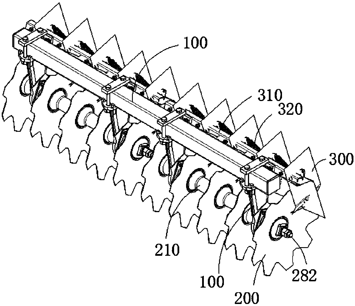
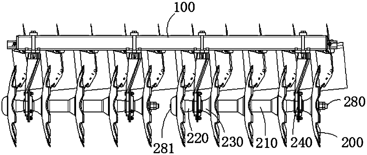
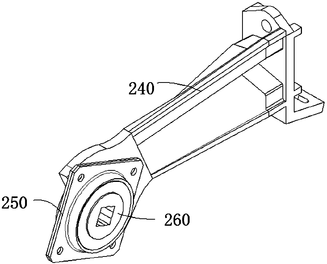
[0040] Refer to attached figure 1 , figure 2 , image 3 and Figure 4 As shown, a front rake group for a disc harrow in this embodiment includes a beam 100 and a plurality of rake blades 200 connected to the beam 100, and the blades 200 are divided into two groups with the same left and right sides and are arranged in a line below the beam 100. The rakes 200 in the middle of each group are separated by an inter-pipe 210, and the rakes 200 near both ends of the rake group are separated from the middle rakes 200 by splicing the long half-pipe 220 and the short half-pipe 230. A bearing bracket 240 is installed between the half tube 220 and the short half tube 230, the bearing bracket 240 is fixedly connected to the beam 100, the lower end of the bearing bracket 240 is fixedly connected to the bearing seat 250, and the bearing seat 250 is equipped with a square hole bearing 260 and a rake piece 200 , the middle pipe 210, the long half pipe 220 and the short half pipe 230 are a...

Embodiment 2

[0047] Refer to attached figure 1 , figure 2 , image 3 , Figure 4 and Figure 5 As shown, the method of using the front harrow group for a disc harrow in this embodiment is that the harrow group is fixed on the frame, and the tractor drives the harrow group on the frame to plow the land.

[0048] The usage method of this embodiment comprises the following steps:

[0049] S100, installing, fixing multiple harrow groups on the disc harrow frame;

[0050] S200, traction, the tractor pulls the disc harrow forward to drive the harrow group forward;

[0051] S300, arable land, the harrow blade 200 is embedded in the land, and the land is broken and cultivated as the tractor advances;

[0052] S400. Cleaning. After finishing the plowing, the harrow group is disassembled for cleaning and maintenance.

[0053] The specific method of step S300 in this embodiment is to embed the rake blade 200 into the land, and as the disc harrow advances, the square hole bearing 260 rotates t...


PUM


Abstract

The invention relates to a front harrow set for a disc harrow and a using method of the front harrow set and belongs to the technical field of disc harrows. The front harrow set comprises a cross beamand a plurality of harrow sheets connected with the cross beam; the harrow sheets are divided into a left group and a right group which are identical in number and are arrayed below the cross beam; the harrow sheets in the middle of each group are separated by partition pipes, the harrow sheets close to the two ends in the harrow set and the middle harrow sheets are separated by splicing long semi-partition pipes with short semi-partition pipes, and a bearing bracket is mounted between each long semi-partition pipe and the corresponding short semi-partition pipe and fixedly connected with thecross beam; the lower end of each bearing bracket is fixedly connected with a bearing base, a square hole bearing is mounted in each bearing base, and square holes with the same size are formed in the harrow sheets, the partition pipes, the long semi-partition pipes and the short semi-partition pipes and communicated with the square hole bearings; a square shaft is fixed in each square hole. Theharrow set has the advantages of stable integral structure, uniform harrow sheet spacing and good tillage effect.

Description

technical field [0001] The invention belongs to the technical field of disc harrows, and more specifically relates to a front harrow group for disc harrows and a usage method thereof. Background technique [0002] The disc harrow is a traditional tillage tool in agricultural production, and it used to be one of the necessary farm tools for farmers. It is also one of the Chinese martial arts equipment, which evolved from farm tools. Iron-toothed rakes, with sharp teeth like nails, are highly aggressive and also function as weapons. Disc harrow is based on the principle of harrowing, with groups of concave discs as working parts. The plane of the cutting edge of the harrow is perpendicular to the ground and has an adjustable deflection angle with the direction of the unit. During operation, the rake rolls forward under the action of tractor traction and soil reaction force, the cutting edge of the rake cuts into the soil, cuts off the grass roots and crop residues, and makes...

Claims


Application Information

Patent Timeline
Patent Type & Authority Applications(China)
IPC IPC(8): A01B23/06A01B23/00A01B21/08
CPCA01B21/08A01B23/00A01B23/06
Inventor 刘汉武刘繁华王晓燕程俊争王福礁李兴凯
Owner 北京德邦大为科技股份有限公司
Why Eureka
Try Eureka