Filter element cleaning equipment for industrial dehumidifier

A technology for cleaning equipment and dehumidifiers, applied in the direction of filtration separation, filter regeneration, separation methods, etc., which can solve the problems of low manual cleaning efficiency, inability to clean filter elements, and physical injury to workers, so as to reduce manual labor intensity and high cleaning efficiency , the effect of low labor intensity

Active Publication Date: 2019-04-05
ZHEJIANG OULUN ELECTRIC
View PDF6 Cites 2 Cited by
  • Summary
  • Abstract
  • Description
  • Claims
  • Application Information

AI Technical Summary

Problems solved by technology

[0004] In order to solve the above problems, the present invention provides a filter element cleaning device for industrial dehumidifiers. The present invention can solve the problem that the filter elements of existing dehumidifiers are usually cleaned manually. The manual cleaning efficiency is low, the labor intensity is high, and the It can clean and collect the adhered velvet, cotton wool and broken ends on the surface of the filter element, and the waste is easy to cause harm to the worker's body during manual cleaning, and the filter element cannot be cleaned automatically. The operation is complicated, labor-intensive and cleaning efficiency is low. and other problems, it can realize the function of automatic cotton suction and cleaning on the surface of the filter element, which can effectively reduce the labor intensity, ensure the cleaning effect, improve the cleaning efficiency, and can effectively remove the velvet, cotton wool and Sweeping and collecting the broken ends avoids the waste material that may cause harm to the workers during manual cleaning. The degree of automation is high, and it has the advantages of simple and convenient operation, low labor intensity and high cleaning efficiency.

Method used


Image

  • Filter element cleaning equipment for industrial dehumidifier
  • Filter element cleaning equipment for industrial dehumidifier
  • Filter element cleaning equipment for industrial dehumidifier

Examples


Embodiment Construction

[0027] In order to make the technical means, creative features, goals and effects achieved by the present invention easy to understand, the present invention will be further described below in conjunction with specific illustrations. It should be noted that, in the case of no conflict, the embodiments in the present application and the features in the embodiments can be combined with each other.

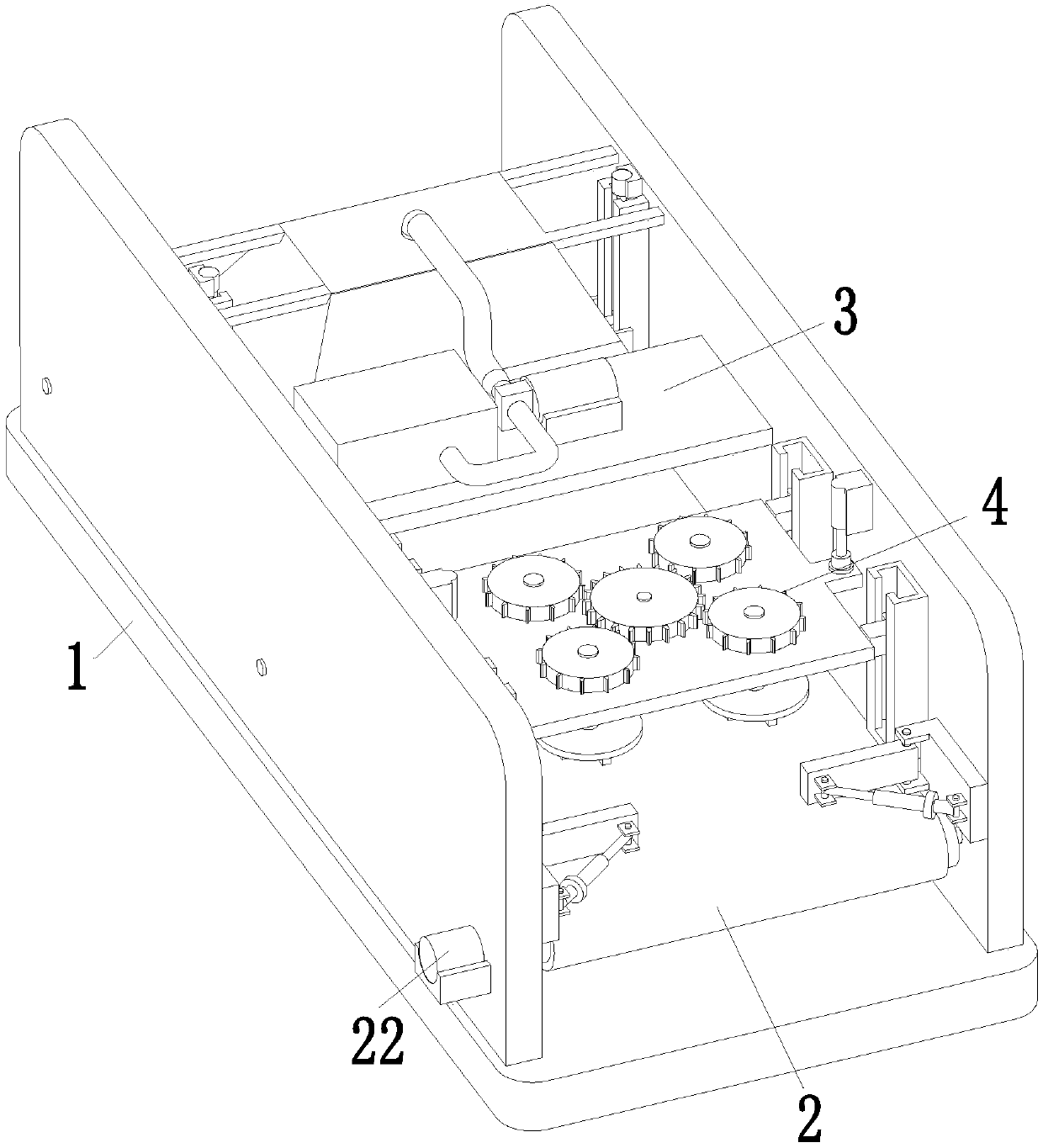
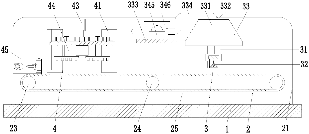
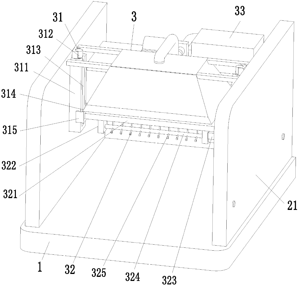
[0028] Such as Figure 1 to Figure 4 As shown, a filter cleaning device for an industrial dehumidifier includes a bottom plate 1, a conveying frame 2, a cotton suction device 3 and a cleaning device 4. The upper end of the bottom plate 1 is provided with a conveying frame 2, and the left side of the upper end of the conveying frame 2 is installed with a Cotton suction device 3, a cleaning device 4 is installed on the right side of the upper end of the conveyor frame 2, and the cleaning device 4 is located on the right side of the cotton suction device 3; The cleaning device 4 can clea...


PUM


Abstract

The invention relates to filter element cleaning equipment for an industrial dehumidifier. The filter element cleaning equipment for the industrial dehumidifier comprises a bottom plate, a conveying rack, a cotton absorbing device and a cleaning device, wherein the conveying rack is arranged at the upper end of the bottom plate; the cotton absorbing device is mounted on the left side of the upperend of the conveying rack; the cleaning device is mounted on the right side of the upper end of the conveying rack; and the cleaning device is positioned on the right side of the cotton absorbing device. The problems that when a filter element of an existing dehumidifier is cleaned, the filter element is always cleaned manually, the manual cleaning efficiency is low, the labor intensity is large,fluffs, cotton fibers and broken ends which are attached to the surface of the filter element cannot be swept or collected, moreover, during manual cleaning, waste materials easily harm health of workers, the filter element cannot be swept automatically, operation is complicated, the labor intensity is high, cleaning efficiency is low and the like can be solved, functions of absorbing cotton of the surface of the filter element and cleaning the surface of the filter element can be fulfilled automatically, and the filter element cleaning equipment for the industrial dehumidifier has the advantages of simplicity and convenience in operation, low labor intensity, high cleaning efficiency and the like.

Description

technical field [0001] The invention relates to the field of filter element cleaning equipment, in particular to filter element cleaning equipment for industrial dehumidifiers. Background technique [0002] Dehumidifiers play a vital role in textile mills. During the production process of textile workshops, dehumidifiers keep the environment at a suitable humidity. If the moisture-proof and dehumidification measures are not perfect, a large number of textiles will be damp and scrapped. In the textile workshop of the textile factory, there will be countless velvet, cotton wool, and broken ends flying around. The dehumidifier will suck a large amount of textile waste into the body during work. After long-term use, it is necessary to clean the interior of the dehumidifier filter element for cleaning. [0003] The filter element of the existing dehumidifier is usually cleaned manually, the efficiency of manual cleaning is low, and the labor intensity is high. The waste is easy...

Claims


Application Information

Patent Timeline
Patent Type & Authority Applications(China)
IPC IPC(8): B01D41/04
CPCB01D41/04
Inventor 方志斌陈先勇
Owner ZHEJIANG OULUN ELECTRIC
Why Eureka
Try Eureka