System and method for light beam shaping welding

A beam shaping and welding system technology, applied in laser welding equipment, welding equipment, metal processing equipment, etc., can solve problems such as inability to realize automatic adjustment

Pending Publication Date: 2019-04-05
浙江雷拉激光科技有限公司
View PDF7 Cites 0 Cited by
  • Summary
  • Abstract
  • Description
  • Claims
  • Application Information

AI Technical Summary

Problems solved by technology

Although this method can adjust the direction of the laser beam, the adjustment of the direction of the laser beam depends on manual adjustment, and automatic adjustment cannot be realized.

Method used


Image

  • System and method for light beam shaping welding
  • System and method for light beam shaping welding
  • System and method for light beam shaping welding

Examples


Embodiment 1

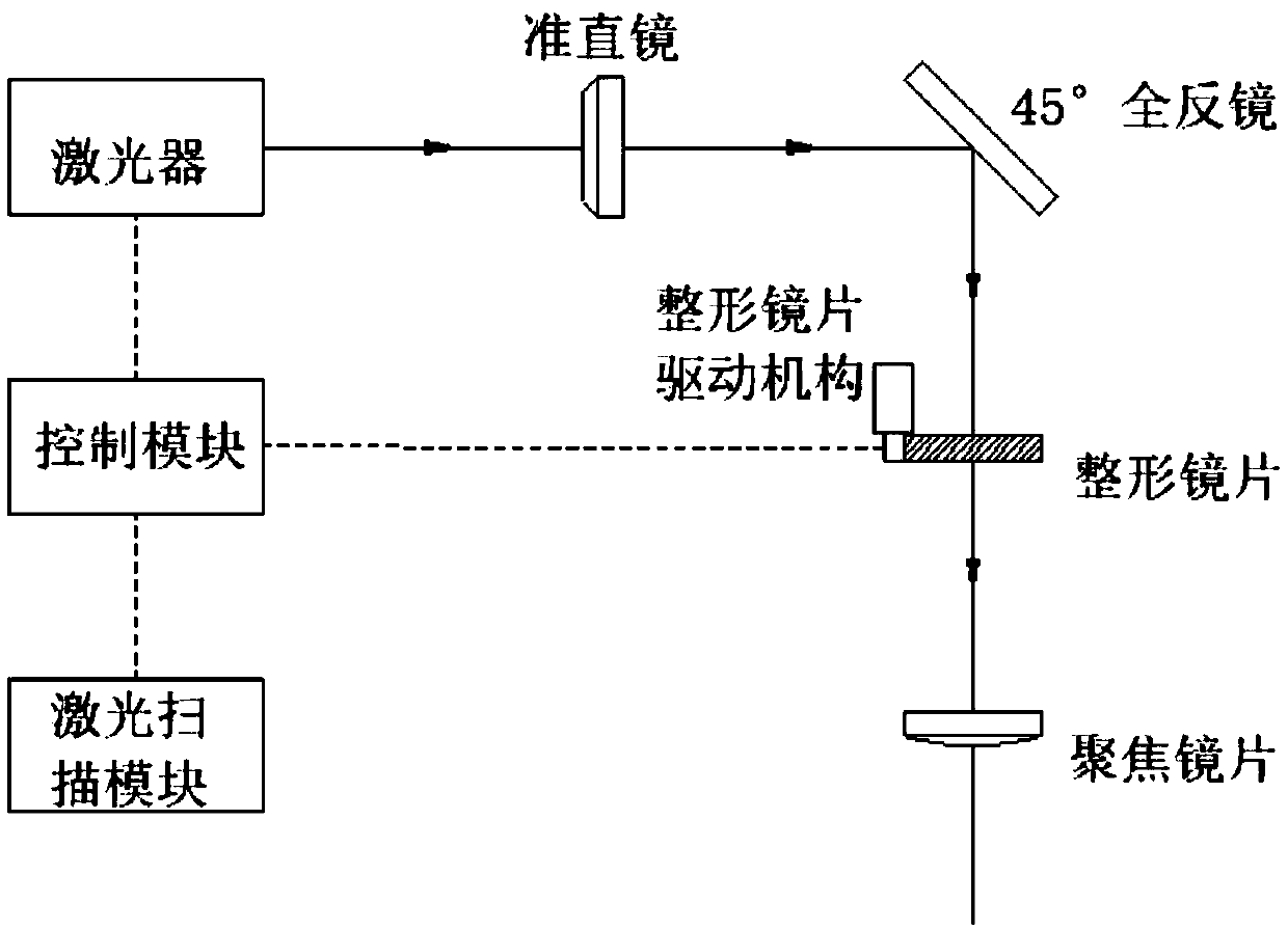
[0031] This embodiment provides a beam shaping welding system, such as figure 1 As shown, including laser, collimating mirror and 45° total reflection mirror, also includes:

[0032] Laser scanning module, used to scan the welding path;

[0033] A control module electrically connected to the laser scanning module, used to control the welding head to perform welding;

[0034] A solder joint electrically connected to the control module.

[0035] Specifically, in this embodiment, the laser scanning module is a laser scanner, and the laser scanner uses a rapidly oscillating (or rotating) mirror to emit a laser beam with highly concentrated energy, so that the output angle of the laser beam increases with the emission angle. The movement of the mirror produces continuous changes, thus projecting a scanning line. Although the laser scanner has only one photodetector and one light source, due to the high scanning frequency of the mirror, the laser scanner can obtain image informati...

Embodiment 2

[0046] Compared with Embodiment 1, this embodiment provides a welding example of a curved path, and the rest are the same as Embodiment 1, and the same parts will not be repeated here.

[0047] The working process of the curved path welding example provided in this embodiment is:

[0048] Such as Figure 6As shown, the welding operation starts from the starting point, and the long axis of the light spot is kept perpendicular to the welding path (or the angle required by the process) and moves along the predetermined path. During the welding process, the control module controls the direction and rotation angle of the plastic lens 1 to adjust in real time according to the path direction , so as to obtain the weld seam shown in the picture, complete the welding of the picture path, and the rotation angle of the plastic lens is 0-90°; thus, the welding of the curved path is completed. The figure is a plane curve, if it is a space curve, it can also be realized with the Z-directio...

Embodiment 3

[0050] Compared with Embodiment 1, this embodiment provides an example of welding with an elliptical path, and the rest are the same as Embodiment 1, and the same parts will not be repeated here.

[0051] The working process of the elliptical path welding example provided by this embodiment is:

[0052] Such as Figure 7 As shown, the welding operation can be started at any point on the path shown in the figure. The control module controls the rotation angle of the plastic lens 1 to make real-time adjustments according to the welding path. After completing the welding operation of the entire elliptical path, the rotation angle of the plastic lens is 0-360 °, thus completing the welding of the elliptical path.

[0053] It should be noted that the present invention can meet the welding operation of complex spatial curve paths, and is not limited to the welding of rectangular paths, curved paths and elliptical paths, and the weld seam properties are highly consistent throughout ...


PUM


Abstract

The invention discloses a system and a method for light beam shaping welding. The system comprises a laser device, a collimating mirror and a 45-degree total-reflecting mirror. The system further comprises a laser scanning module used for scanning a welding path, a control module electrically connected with the laser scanning module, and used for controlling a welding head to weld, and the weldinghead electrically connected with the control module. According to the system and the method for light beam shaping welding, follow-up welding is realized by combining a light beam shaping technologywith a laser scanning technology; accurate pre-judgement for the welding path is realized by virtue of a laser scanning technology; and real-time adjustment for the direction of light spots and the relative position of the welding path is realized by adjusting the direction and the angle of the welding head, and the rotation angle of a shaping lens.

Description

technical field [0001] The invention relates to the field of welding technology, in particular to a beam shaping welding system and method. Background technique [0002] Beam shaping welding is laser welding. Laser welding is an efficient and precise welding method that uses a high-energy-density laser beam as a heat source. In the 1970s, it was mainly used for welding thin-walled materials and low-speed welding. The welding process is heat conduction, that is, the laser radiation heats the surface of the workpiece, and the surface heat diffuses to the inside through heat conduction. By controlling the width, energy, peak power and repetition frequency of the laser pulse and other parameters to melt the workpiece and form a specific molten pool. Due to its unique advantages, it has been successfully applied in the precision welding of micro and small parts. [0003] The welding method using beam shaping technology has many advantages, but the welding direction cannot be ad...

Claims


Application Information

Patent Timeline
Patent Type & Authority Applications(China)
IPC IPC(8): B23K26/24B23K26/08B23K26/082B23K26/064B23K26/60B23K26/70
CPCB23K26/064B23K26/0643B23K26/082B23K26/0884B23K26/24B23K26/60B23K26/702
Inventor 李晶宋君路凯
Owner 浙江雷拉激光科技有限公司
Why Eureka
Try Eureka