Nozzle enlarger for pipe materials

A technology of expanding machine and nozzle, applied in the field of nozzle expanding machine, it can solve problems such as affecting work efficiency and product quality, low degree of automation, rough finished product, etc., and achieve the effect of reasonable design, reduced labor intensity and time saving.

Inactive Publication Date: 2019-04-05
佘巧莲
View PDF4 Cites 2 Cited by
  • Summary
  • Abstract
  • Description
  • Claims
  • Application Information

AI Technical Summary

Problems solved by technology

At present, the existing flaring forming devices generally can only expand the radial dimension of the end of the pipe into a flaring portion, and there is a lack of a flaring forming device that can simultaneously form an annular groove that can carr

Method used

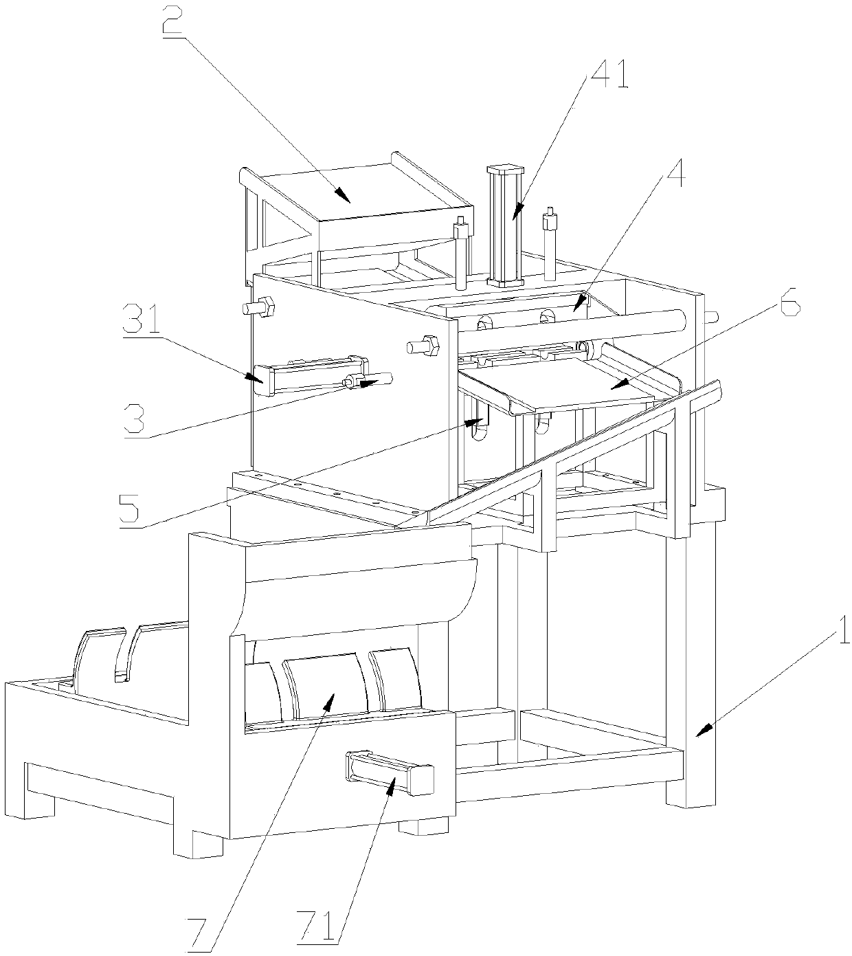

Image

  • Nozzle enlarger for pipe materials
  • Nozzle enlarger for pipe materials
  • Nozzle enlarger for pipe materials

Examples


Embodiment Construction

[0042] The following will clearly and completely describe the technical solutions in the embodiments of the present invention with reference to the accompanying drawings in the embodiments of the present invention. Obviously, the described embodiments are only some, not all, embodiments of the present invention. Based on the embodiments of the present invention, all other embodiments obtained by persons of ordinary skill in the art without creative efforts fall within the protection scope of the present invention.

[0043] In describing the present invention, it is to be understood that the terms "opening", "upper", "lower", "thickness", "top", "middle", "length", "inner", "surrounding" etc. Indicating orientation or positional relationship is only for the convenience of describing the present invention and simplifying the description, and does not indicate or imply that the components or elements referred to must have a specific orientation, be constructed and operated in a sp...


PUM


Abstract

The invention discloses a nozzle enlarger for pipes. The nozzle enlarger for the pipes comprises a support which is used for supporting the nozzle enlarger for operation; the support is provided withfeeding racks for feeding the pipes; the support is provided with an enlarging device for pipe forming; the support is provided with a clamping device for pipe clamping; the support is provided with acontrol device for feeding and discharging during pipe forming; and the support is provided with a discharging rack for discharging enlarged pipes, and a bundling device for bundling the pipes is arranged on one side of the support. According to the nozzle enlarger for the pipes storage space of the feeding racks is enlarged through the superposition arrangement of the feeding racks without increasing the area occupied; the automatic nozzle enlargement, and automatic feeding and pushing of the pipes are realized through a first cylinder, a second cylinder and a dual-shaft cylinder, the time is saved, the design is reasonable, the working efficiency is improved, and the product quality and precision are further improved; and the nozzle enlarger replaces the traditional manual flaring, thusthe working efficiency is improved, and the labor intensity of staff is reduced.

Description

technical field [0001] The invention relates to the field of pipe materials, in particular to a nozzle enlarger for pipe materials. Background technique [0002] Flaring refers to the processing method of expanding the radial dimension of the end of the pipe or hollow part. After the CPVC plastic pipe is formed, one end needs to be flared to facilitate the pipe butt joint, and the pipe is flared on the special equipment for flare. When flaring, one end of the pipe is heated and softened at a fixed length, and then the unheated end of the pipe is fixed on the flaring forming device through the pipe clamping assembly, and the heating and softening end is set on the same line as the pipe flaring forming assembly, and the heating and softening end passes through The flaring and shaping mold core performs flaring operation, and finally it is cooled and formed under the cooling action of the cooling component, and the flaring part whose size matches the flaring and shaping mold c...

Claims


Application Information

Patent Timeline
IPC IPC(8): B29C57/04
CPCB29C57/04
Inventor 佘巧莲
Owner 佘巧莲
Why Eureka
Try Eureka