Siphon electric energy storage equipment and method

A technology for storage equipment and electric energy storage devices, applied in siphons, mechanical equipment, current collectors, etc., can solve problems such as complex fixed building facilities, inapplicability to small power-demanding places, and complex small and medium-sized power generation equipment

Active Publication Date: 2019-04-05
XIAN TECHNOLOGICAL UNIV
View PDF5 Cites 0 Cited by
  • Summary
  • Abstract
  • Description
  • Claims
  • Application Information

AI Technical Summary

Problems solved by technology

[0002] Hydroelectric power generation is to use rivers, lakes, etc. to flow water with potential energy from high places to low places, convert the potential energy contained in it into kinetic energy of water turbines, and then use water turbines as the driving force to drive generators to generate electricity, and use water power to drive hydraulic machinery to rotate. Water energy is converted into mechanical energy. If a generator is connected to the water turbine, the generator can generate electricity with the rotation of the water turbine. At this time, the mechanical energy is converted into electrical energy. In a sense, hydropower is the conversion of the potential energy of water into The process of converting mechanical energy into electrical energy, but the current hydropower generation is mainly for river beaches where large-scale dam-damping hydropower stations are easy to build, and the fixed building facilities are relatively complicated
[0003] However, the existing small and medium-sized power generation equipment is relatively complicated and cannot be applied to small power-demanding places

Method used


Image

  • Siphon electric energy storage equipment and method
  • Siphon electric energy storage equipment and method

Examples


Embodiment 1

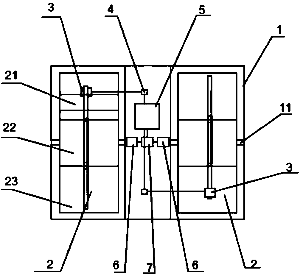
[0026] Such as figure 1 As shown, a siphon electric energy storage device includes a fixing device 1, an energy generating device 2, a power generating device 3, a rectifying device 4 and an electric energy storage device 5, the energy generating device 2 is arranged on the fixing device 1, and the power generating device 3 is arranged inside the energy generating device 2, the rectifying device 4 is connected to the generating device 3, and the rectifying device 4 is connected to the electric energy storage device 5.

[0027] The energy generating device 2, the power generating device 3, the rectifying device 4 and the electric energy storage device 5 are provided in at least one group.

[0028] At least two energy generating devices 2 are arranged on one fixing device 1, and the two energy generating devices 2 are set opposite to each other; A rectifying device 4, an electric energy storage device 5 and a motor 6 for driving the rotating shaft are arranged between the devic...

Embodiment 2

[0038] A storage method for a siphon electric energy storage device, comprising the following steps:

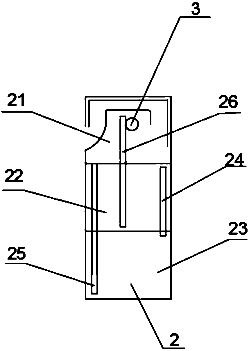
[0039] 1). Generation of energy: the water in the first water holding device 21 of the energy generating device 2 enters the third water holding device 23 through the second pipeline 25, the water level in the third water holding device 23 rises, and passes through the first pipe The road 24 compresses the air to the second water holding device 22 , the air in the second water holding device 22 increases, the compressed air lowers the water level, and under the pressure of the air, the water in the second water holding device 22 passes through the third pipeline 26 Press out to the upper part of the first water holding device 21, and the water flow that is pressed out falls in a parabola to generate gravitational potential energy;

[0040] 2) Generation of electric energy: an impeller power generation device 3 is installed at the upper and lower ends of the first water holdin...


PUM


Abstract

The invention discloses siphon electric energy storage equipment and method. The siphon electric energy storage equipment comprises a fixing device, energy generation devices, power generation devices, a rectifying device and an electric energy storage device. The energy generation devices are disposed on the fixing device, the power generation devices are disposed inside the energy generation devices, the rectifying device is connected with the power generation devices, and the rectifying device is connected to the electric energy storage device. The siphon electric energy storage equipment and method do not require the construction of fixed water storage equipment, provides a plurality of energy generation devices which can continuously generate electricity, and can be applied to a smallpower demanding place.

Description

technical field [0001] The invention belongs to the technical field of power generation, and in particular relates to a siphon electric energy storage device and a storage method. Background technique [0002] Hydroelectric power generation is to use rivers, lakes, etc. to flow water with potential energy from high places to low places, convert the potential energy contained in it into kinetic energy of water turbines, and then use water turbines as the driving force to drive generators to generate electricity, and use water power to drive hydraulic machinery to rotate. Water energy is converted into mechanical energy. If a generator is connected to the water turbine, the generator can generate electricity with the rotation of the water turbine. At this time, the mechanical energy is converted into electrical energy. In a sense, hydropower is the conversion of the potential energy of water into The process of converting mechanical energy into electrical energy, but the curre...

Claims


Application Information

Patent Timeline
Patent Type & Authority Applications(China)
IPC IPC(8): F03B13/06F04F10/00H02J7/14
CPCF03B13/06F04F10/00H02J7/1423H02J7/143Y02E10/20Y02E60/16
Inventor 宋旭吴媛王宇栋李锐常行
Owner XIAN TECHNOLOGICAL UNIV
Why Eureka
Try Eureka