A power generation device based on rolling motion

A technology of rolling and motion, applied in the field of power generation devices based on rolling motion, can solve the problems of short effective working time, large wave energy loss, low energy conversion rate, etc., and achieve long effective working time, large power generation and sensitivity. high effect

Active Publication Date: 2022-08-09
DALIAN UNIV OF TECH
View PDF0 Cites 0 Cited by
  • Summary
  • Abstract
  • Description
  • Claims
  • Application Information

AI Technical Summary

Problems solved by technology

However, the existing wave generators still have the following disadvantages: complex structure, excessive friction, high manufacturing cost, prone to failure, low service life, large loss of wave energy, and when the wave is small, it is easy to stop working and cause it to work effectively shorter time
[0004] It is precisely based on this rolling device with extremely high wave energy and mechanical energy conversion efficiency that the present invention designs and installs a simple structure, low cost, strong reliability, high energy efficiency ratio, long effective working time, and economical The power generation device with good efficiency effectively solves the problems of complex structure, high cost, high failure rate, low energy conversion rate and short effective working time of the existing rolling wave power generation device

Method used


Image

  • A power generation device based on rolling motion
  • A power generation device based on rolling motion
  • A power generation device based on rolling motion

Examples


Embodiment Construction

[0024] The technical solutions of the present invention will be further described below with reference to the accompanying drawings and embodiments.

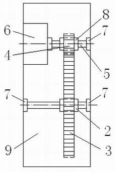
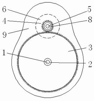
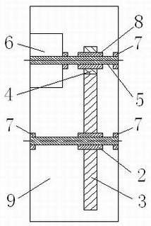
[0025] figure 1 , 2 , 3 show a structure diagram of a rolling type power generation device. In the figure, the power generation device based on rolling motion includes a first shaft 1, a large gear 3, a pinion 4, a second shaft 5, a generator 6, a bearing 7, a first one-way bearing 2, and a second one-way bearing 8 and the rolling device 9 , the generator 6 and the plurality of bearings 7 are fixedly connected to the rolling device 9 . The first rotating shaft 1 is fixedly connected to the rolling device 9 through two bearings 7 , the first one-way bearing 2 is fixedly nested on the first rotating shaft 1 , and the large gear 3 is fixedly nested on the first one-way bearing 2 . The second rotating shaft 5 is connected to the generator 6 and the bearing 7, the second one-way bearing 8 is fixedly nested on the second rotating s...


PUM


Abstract

The utility model relates to a power generation device based on rolling motion, which can be installed in a rolling wave power generation device or a rolling wave breaker, and belongs to the field of new energy using ocean energy to generate electricity. The power generating device includes a first rotating shaft, a first one-way bearing, a large gear, a small gear, a second rotating shaft, a generator, a bearing, a second one-way bearing, and rolling equipment. The first rotating shaft is fixedly connected to the rolling equipment, the first one-way bearing is fixedly nested on the first rotating shaft, the large gear is fixedly nested on the first one-way bearing, the generator and the bearing are fixedly connected to the rolling equipment, and the first one-way bearing is fixedly nested on the first one-way bearing. The two rotating shafts are connected to the generator and the bearing, the second one-way bearing is fixedly nested on the second rotating shaft, and the pinion is fixedly nested on the second one-way bearing, and is located between the generator and the bearing, and is closely meshed with the large gear together. The power generation device has the advantages of simple structure, low cost, high efficiency ratio, high reliability, no pollution, can generate electricity effectively under regular waves and irregular waves, and has good wave absorbing ability.

Description

technical field [0001] The invention relates to a power generation device based on rolling motion, which can be installed in a rolling wave power generation device or a rolling wave breaker, and belongs to the field of new energy using ocean energy to generate electricity. Background technique [0002] In 1974, engineer Salter invented a rolling wave energy conversion device. The design of the device is rigorous and the cross-sectional profile is asymmetrical. The underwater part is arc-shaped, and the device rolls around the rotation axis under the action of waves, and can intercept almost all short waves. The first-order conversion efficiency of this wave energy conversion device in short waves can be close to 100%. [0003] Although wave power research has been developed for decades, dozens of different power generation device designs have emerged to improve power generation efficiency. However, the existing wave generator still has the following shortcomings: complex st...

Claims


Application Information

Patent Timeline
Patent Type & Authority Patents(China)
IPC IPC(8): F03B13/14F03B11/06
CPCF03B11/06F03B13/14F05B2220/706F05B2260/4031Y02E10/20Y02E10/30
Inventor 邹丽宗智姜宜辰李嘉文张桂勇孙铁志李海涛王兴龙张浩然曾智华
Owner DALIAN UNIV OF TECH
Why Eureka
Try Eureka