
An anti-turnover high-temperature corrosion medium delivery pipeline assembly

A technology for high-temperature corrosion and medium transportation, which is applied in the direction of pipes/pipe joints/fittings, piping systems, pipe supports, etc., and can solve problems such as cracks, large loads, and vulnerable welding joints between medium transportation pipes and other pipes, and achieve Ensure the horizontal position accuracy, fix the installation angle, and improve the quality of welding butt joint

Active Publication Date: 2020-06-12
上海宝冶工程技术有限公司 +1
View PDF1 Cites 0 Cited by
  • Summary
  • Abstract
  • Description
  • Claims
  • Application Information

AI Technical Summary

Problems solved by technology

[0004] However, there are the following defects in the prior art: First, due to the inevitable weight of the high-temperature corrosive medium valve and the pipe joint, the horizontally arranged medium conveying pipeline must bear the vertical force caused by the self-weight of the high-temperature corrosive medium valve and the pipe joint. Under the flexural stress, the welded joints between the medium conveying pipeline and other pipes need to bear a large load. A little carelessness will cause cracks at the welded joints between the medium conveying pipeline and other pipes due to load, making The welded butt joint between the medium conveying pipeline and other pipelines becomes a vulnerable point, resulting in the two medium conveying pipelines not being well in a horizontal state; Under the action of self-weight, there is a hidden danger of downward flipping of high-temperature corrosive medium valves

Method used


Image

  • An anti-turnover high-temperature corrosion medium delivery pipeline assembly
  • An anti-turnover high-temperature corrosion medium delivery pipeline assembly

Examples


Embodiment Construction

[0016] The present invention will be further described below in conjunction with the accompanying drawings and specific embodiments.

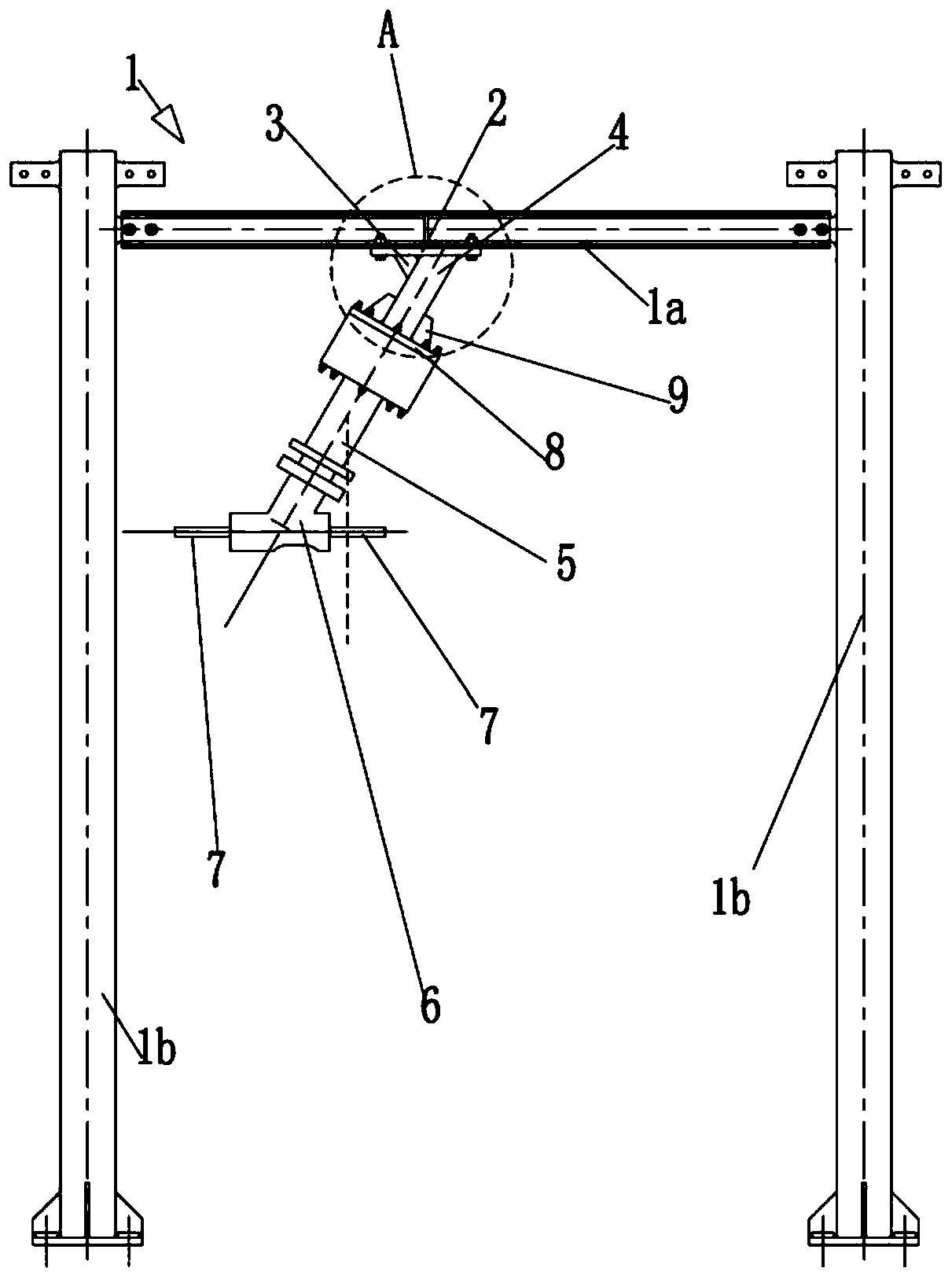
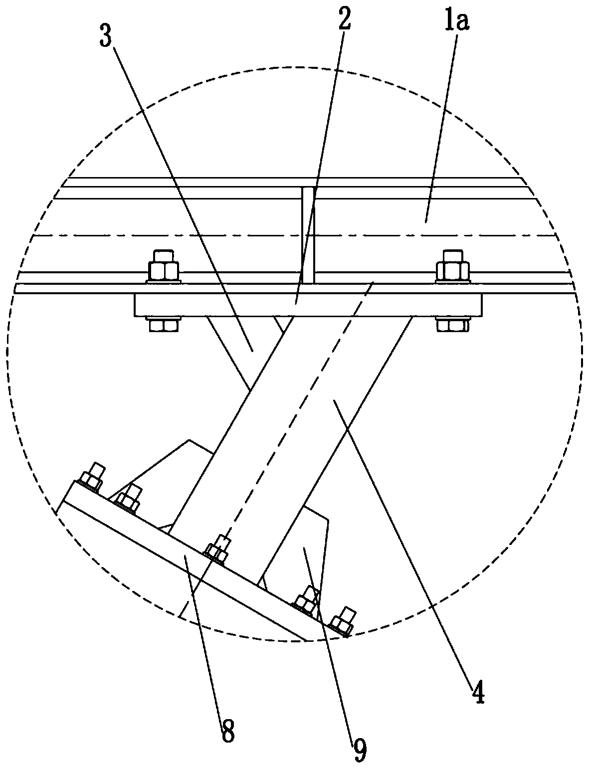
[0017] Such as Figure 1-2 As shown, an anti-turnover high-temperature corrosion medium delivery pipeline assembly includes a high-temperature corrosion medium valve 5, a pipe joint 6, a pair of horizontally extending medium delivery pipelines 7, and a pair of medium delivery pipelines 7 are inserted into the pipe joint 6 respectively. Both ends are connected with the pipe joint 6, and the high-temperature corrosive medium valve 5 is installed in conjunction with the pipe joint 6 to control the on-off state of the pipe joint 6, and the axis of the high-temperature corrosive medium valve 5 is inclined, and the high-temperature corrosive medium valve 5 is matched An anti-turnover fixed foundation is provided. The anti-turnover fixed foundation includes a door-shaped bracket 1, a top plate 2, a rib plate 3, and a central axis tube 4. The top plate...


PUM


Abstract

The invention relates to an anti-overturning type high-temperature corrosive medium conveying pipeline component in the technical field of high-temperature corrosive medium conveying. The anti-overturning type high-temperature corrosive medium conveying pipeline component comprises a high-temperature corrosive medium valve, a pipe joint and a pair of horizontally-extending medium conveying pipes;the high-temperature corrosive medium valve is provided with an anti-overturning fixed foundation in a mated manner, the anti-overturning fixed foundation comprises a door type bracket, a top plate, alifting rib plate and a central shaft pipe, the top plate is horizontally arranged and fixedly mounted on the door type bracket, the central shaft pipe is arranged obliquely, the axis of the centralshaft pipe is coincident with the axis of the high-temperature corrosive medium valve, the upper end of the central shaft pipe and the top plate are fixed, and the lower end of the central shaft pipeis fixedly connected with the high-temperature corrosive medium valve; and the lifting rib plate is fixedly connected with the central shaft pipe and the top plate. The pair of medium conveying pipescan be well in a horizontal state, the installing stability can be ensured, and the high-temperature corrosive medium valve is prevented from overturning.

Description

technical field [0001] The invention relates to the technical field of high-temperature corrosive medium transportation, in particular to a high-temperature corrosive medium transportation pipeline assembly. Background technique [0002] When high-temperature corrosive media are transported over long distances, special piping systems are required, such as molten salt. Such a pipeline system is equipped with a high-temperature corrosive medium valve, such as an authorized patent of the applicant with a patent number of 201610008742.8. The valve body dissipates heat and cools down, so that the internal medium temperature is lower than the melting point, and the freezing valve is closed; otherwise, the valve body is heated and heated. , so that the temperature of the internal medium is higher than the melting point, the freezing valve is opened, and the on-off state of the valve is controlled by adjusting the temperature of the high-temperature corrosive medium. The high-tempe...

Claims


Application Information

Patent Timeline
Patent Type & Authority Patents(China)
IPC IPC(8): F17D3/01F16L3/00
CPCF16L3/00F17D3/01
Inventor 杨天君陆凯秦叶民张博张科石佳文徐杰
Owner 上海宝冶工程技术有限公司
Learn More