Smoke gas inlet structure of fire tube boiler

A fire tube boiler and flue gas technology, applied in the field of fire tube boilers, can solve problems such as stable product quality affecting production, equipment safety, easy damage to the welding seam between heat exchange tubes and tube sheets, leakage of heat exchange tubes and tube sheets, etc. problems, to achieve safe and reliable operation, prevent leakage, and protect the welding seam.

Pending Publication Date: 2019-04-05
SUZHOU HAILU HEAVY IND
View PDF0 Cites 1 Cited by
  • Summary
  • Abstract
  • Description
  • Claims
  • Application Information

AI Technical Summary

Problems solved by technology

However, the connection welds between the heat exchange tubes and the tube sheets are exposed to the high-temperature flue gas, and are washed by the high-temperature flue gas for a long time. During the operation of the boiler, the connection parts between the heat exchange tubes and the tube sheets are repeatedly subjected to thermal deformation and thermal shock. And the pull-off force, so the connection weld between the heat exchange tube and the tube sheet is very easy to damage
Once the connection weld between the heat exchange tube and the tube sheet is damaged, there will be leakage between the heat exchange tube and the tube sheet, and the tube sheet, heat exchange tube and other components will be eroded, which will directly affect the stability of production and the quality of the product. Quality, equipment safety

Method used


Image

  • Smoke gas inlet structure of fire tube boiler
  • Smoke gas inlet structure of fire tube boiler

Examples


Embodiment Construction

[0014] The present invention will be further described in detail below in conjunction with the accompanying drawings and preferred embodiments.

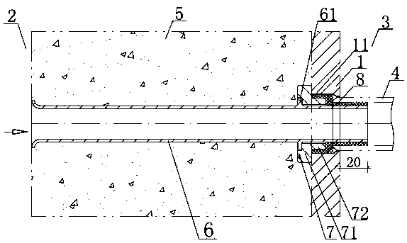
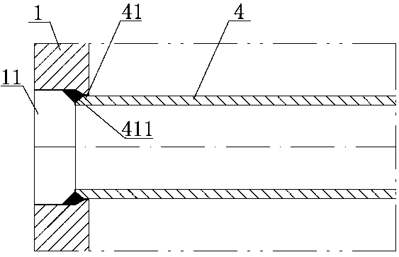
[0015] like figure 1 , figure 2 As shown, the flue gas inlet structure of the fire tube boiler includes: a tube plate 1, one side of the tube plate 1 is the smoke box side 2, and the other side of the tube plate 1 is the water side 3. The nozzle of each heat exchange tube 4 on the water side 3 extends into a tube hole 11 of the tube sheet 1 , and the nozzle of each heat exchange tube 4 is welded and sealed to the corresponding tube hole 11 . The nozzle 41 of each heat exchange tube 4 extends into the end of the tube hole 11 near the water side 3, and the nozzle 41 of each heat exchange tube 4 is welded and sealed to the inner wall of the tube hole 11 near the water side 3 . The nozzle 41 of each heat exchange tube 4 is provided with a welding groove 411 , and the welding groove 411 is fully welded to the tube sheet 1 .

[0016] ...


PUM


Abstract

The invention discloses a smoke gas inlet structure of a fire tube boiler. The smoke gas inlet structure comprises a tube plate, wherein one side of the tube plate is a smoke box side, the other sideof the tube plate is a water path side; the tube hole of each heat exchange tube at the water path side extends into a tube hole of the tube plate; the tube hole of each heat exchange tube is welded,sealed and fixed with the tube hole correspondingly; the tube hole of each heat exchange tube extends into one end, close to the water path side, of the tube hole; the tube hole of each heat exchangetube is welded, sealed and fixed with the inner wall, close to the water path side, of the tube hole; a high-temperature fire-resistant cast layer is arranged between the tube plate and the smoke box;ceramic sleeves which are in one-to-one correspondence to the heat exchange tubes are embedded and fixed in the high-temperature fire-resistant cast layer; one end of each ceramic sleeve communicateswith the smoke box, and the other end of each ceramic sleeve extends into the corresponding heat exchange tube; a ceramic protective sleeve is further arranged in each tube hole; and each ceramic protective tube sleeves the ceramic sleeve in each tube hole. The smoke gas inlet structure has the advantages that a welding seam between the tube plate and the heat exchange tube can be effectively protected, and the fire tube boiler can be guaranteed to safely and reliably operate.

Description

technical field [0001] The invention relates to the technical field of fire tube boilers, in particular to the flue gas inlet structure of the fire tube boilers. Background technique [0002] At present, the structure of the flue gas inlet of a fire tube boiler mainly includes: a tube plate, one side of the tube plate is the smoke box side, and the other side of the tube plate is the water side, and each heat exchange tube on the water side The nozzles all extend into a tube hole of the tube sheet, and the nozzles of each heat exchange tube are welded and sealed to the end corresponding to the tube hole close to the smoke box. The high-temperature flue gas entering the smoke box enters the heat-exchanging tube through the nozzle of the heat-exchanging tube, and the high-temperature flue gas in the heat-exchanging tube releases heat on the water side. [0003] The connection weld between the heat exchange tube and the tube sheet plays a role of isolating the high-temperature...

Claims


Application Information

Patent Timeline
Patent Type & Authority Applications(China)
IPC IPC(8): F28F9/18F22B9/10
CPCF28F9/182F22B9/10
Inventor 朱泓钱飞舟顾君健石永军
Owner SUZHOU HAILU HEAVY IND
Why Eureka
Try Eureka