A device and method for measuring the rotation angle of a rotating shaft

A technology for measuring the rotation angle and rotating shaft, which is applied in the detection field, can solve the problems such as the inability to measure the rotating shaft angle of CNC machine tools, reduce the measurement process, etc., achieve the effect of continuous measurement, meet the requirements of precision measurement, and simplify the measurement device and measurement method

Active Publication Date: 2021-07-02
SHANGHAI MICRO ELECTRONICS EQUIP (GRP) CO LTD
View PDF5 Cites 0 Cited by
  • Summary
  • Abstract
  • Description
  • Claims
  • Application Information

AI Technical Summary

Problems solved by technology

[0004] The purpose of the present invention is to provide a rotating shaft angle measuring device and method to solve the problem that the prior art cannot continuously measure the rotating shaft angle of a numerically controlled machine tool within 360°, so as to reduce the measurement process and simplify the measurement device Purpose

Method used


Image

  • A device and method for measuring the rotation angle of a rotating shaft
  • A device and method for measuring the rotation angle of a rotating shaft
  • A device and method for measuring the rotation angle of a rotating shaft

Examples


Embodiment 1

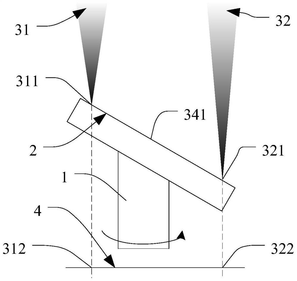
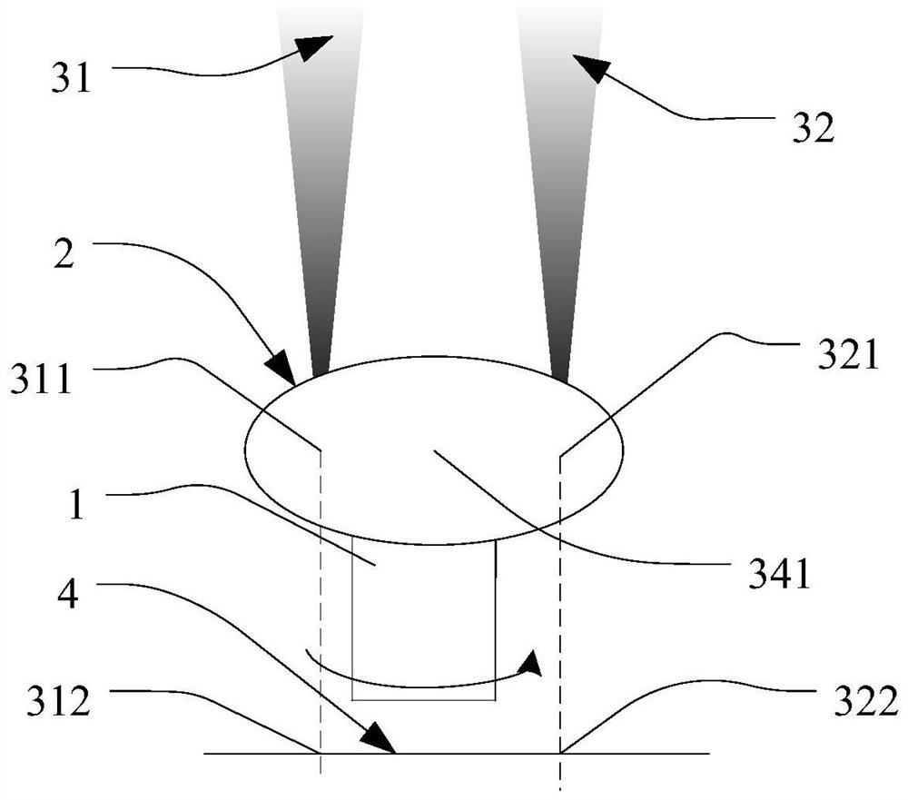
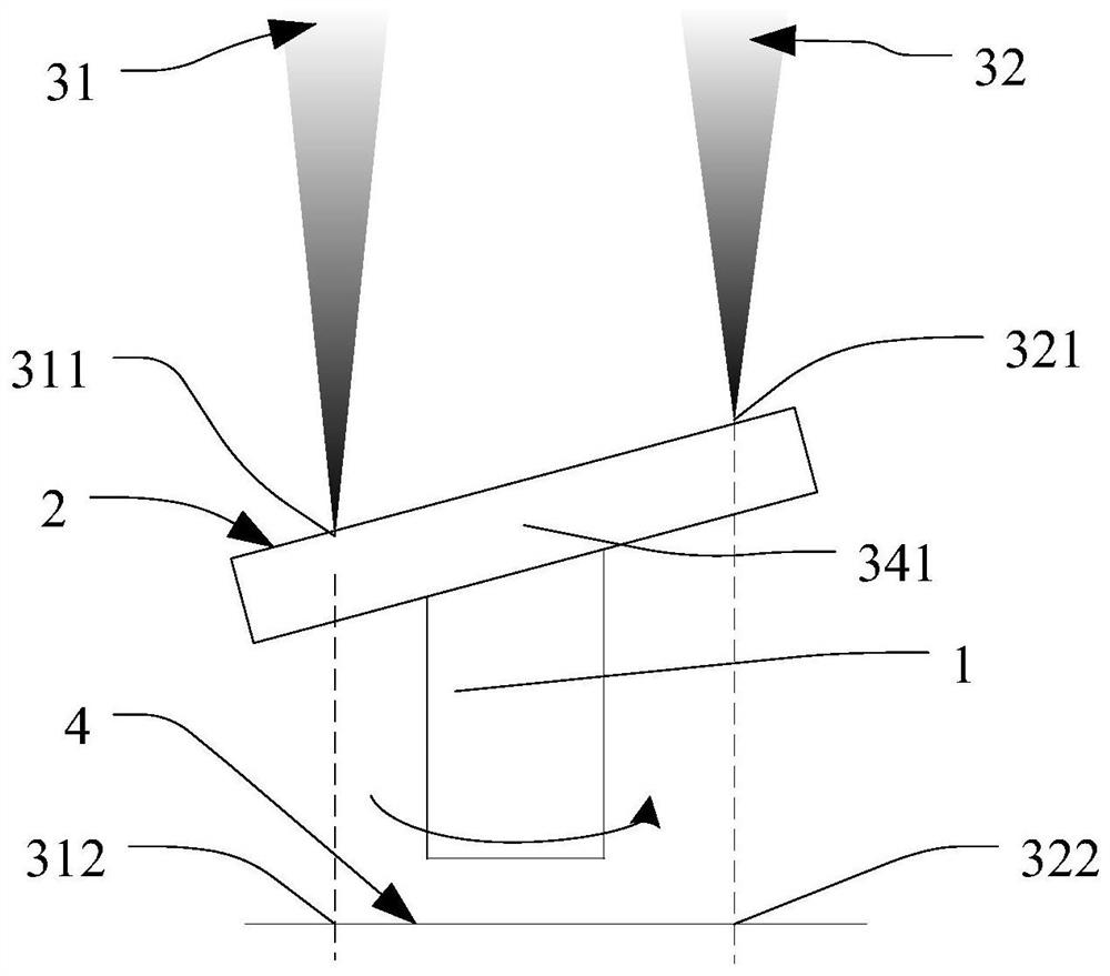
[0059] see figure 1 , in the first embodiment provided by the present invention, the displacement sensor module includes a first displacement sensor 31 and a second displacement sensor 32, the first displacement sensor 31 corresponds to the measurement surface 2 with a first measurement Point 311, the second displacement sensor 32 corresponds to the second measurement point 321 on the measurement surface 2, the first measurement point 311 has a first measurement point projection 312 on the projection plane 4, and the second measurement point 321 is in the projection There is a second measurement point projection 322 on the plane 4. The projection plane 4 is a plane perpendicular to the axis of the rotating shaft. When the rotating shaft 1 rotates, the position of the sensor module remains unchanged, while the first measuring point projection 312 and The position of the second measurement point projection 322 remains unchanged. In addition, the rotating shaft rotation angle mea...

Embodiment 2

[0081] see Figure 8 , wherein the displacement sensor module includes a third displacement sensor 33, the third displacement sensor 33 corresponds to a third measurement point 331 on the measurement surface 2, and the projection plane 4 is perpendicular to the shaft axis A plane of , the third measurement point 331 has a third measurement point projection 332 on the projection plane 4, the intersection point of the shaft axis and the measurement surface is defined as the measurement surface origin 341, the third measurement point 331 and the origin 341 of the measurement surface are defined as the second measurement reference line, and the angle between the second measurement reference line and the axis of the rotating shaft is α. In addition, the rotating shaft angle measuring device also includes a A rotation angle processing unit (not shown in the figure), the rotation angle processing unit is used to calculate the rotation angle of the rotating shaft 1 after receiving the...


PUM


Abstract

The invention provides a rotating shaft rotation angle measuring device and method, comprising a rotating shaft with a measuring surface and a displacement sensor module, the angle between the plane where the measuring surface is located and the axis of the rotating shaft is α, α∈ (0.5nπ, 0.5(n+1)π), the displacement sensor module corresponds to a measurement point on the measurement surface, firstly, the displacement sensor module measures the relationship between the measurement point and the displacement sensor module The distance between the groups is obtained by obtaining the measured value, and then the functional relationship between the measured value and the rotating shaft angle is obtained through calculation, and then the angle of the rotating shaft angle is obtained indirectly. The rotating shaft angle measuring device and method realize the rotating shaft at 360 The continuous angle measurement in the range of ° achieves the purpose of simplifying the measuring device and measuring method.

Description

technical field [0001] The invention belongs to the technical field of detection, and relates to a device and method for measuring the rotation angle of a rotating shaft. Background technique [0002] With the development of CNC machine tool technology, the machining accuracy, flexibility and automation level of CNC machine tools are increasing day by day. Therefore, higher requirements are put forward for the measuring instruments and measurement technology of the performance and parameters of CNC machine tools. In the production process, it is usually necessary to precisely measure or calibrate the angle of the rotating shaft of the CNC machine tool to meet the precision requirements of the CNC machine tool. [0003] In the prior art, angle interferometry and linear interferometry are generally used for precise measurement of the rotation angle of the rotating shaft of a numerically controlled machine tool. In the angle interferometry, the calibration platform is divided ...

Claims


Application Information

Patent Timeline
Patent Type & Authority Patents(China)
IPC IPC(8): G05B19/401
CPCG05B19/401G05B2219/37374
Inventor 肖鹏飞
Owner SHANGHAI MICRO ELECTRONICS EQUIP (GRP) CO LTD
Why Eureka
Try Eureka