Method for measuring three-dimensional errors of machine tool through combination of ball bar instrument and capacitance displacement sensors

A technology of displacement sensor and ballbar, which is applied in the direction of measuring/indicating equipment, metal processing machinery parts, metal processing equipment, etc., can solve the problem that the three-dimensional error of the spindle movement of the machine tool cannot be accurately detected, so as to achieve practicality and improve detection The effect of precision and accurate identification

Active Publication Date: 2021-08-03
HANGZHOU DIANZI UNIV
View PDF5 Cites 0 Cited by
  • Summary
  • Abstract
  • Description
  • Claims
  • Application Information

AI Technical Summary

Problems solved by technology

However, at present, the ballbar can only detect the error change along the rod length direction during the movement of the spindle of the machine tool. Therefore, when using the traditional ballbar to detect the error of the machine tool, it can only analyze the arc trajectory on a single plane, and cannot accurately detect Three-Dimensional Error of Machine Tool Spindle Movement

Method used


Image

  • Method for measuring three-dimensional errors of machine tool through combination of ball bar instrument and capacitance displacement sensors
  • Method for measuring three-dimensional errors of machine tool through combination of ball bar instrument and capacitance displacement sensors
  • Method for measuring three-dimensional errors of machine tool through combination of ball bar instrument and capacitance displacement sensors

Examples


Embodiment Construction

[0036] The present invention will be further described below in conjunction with accompanying drawing.

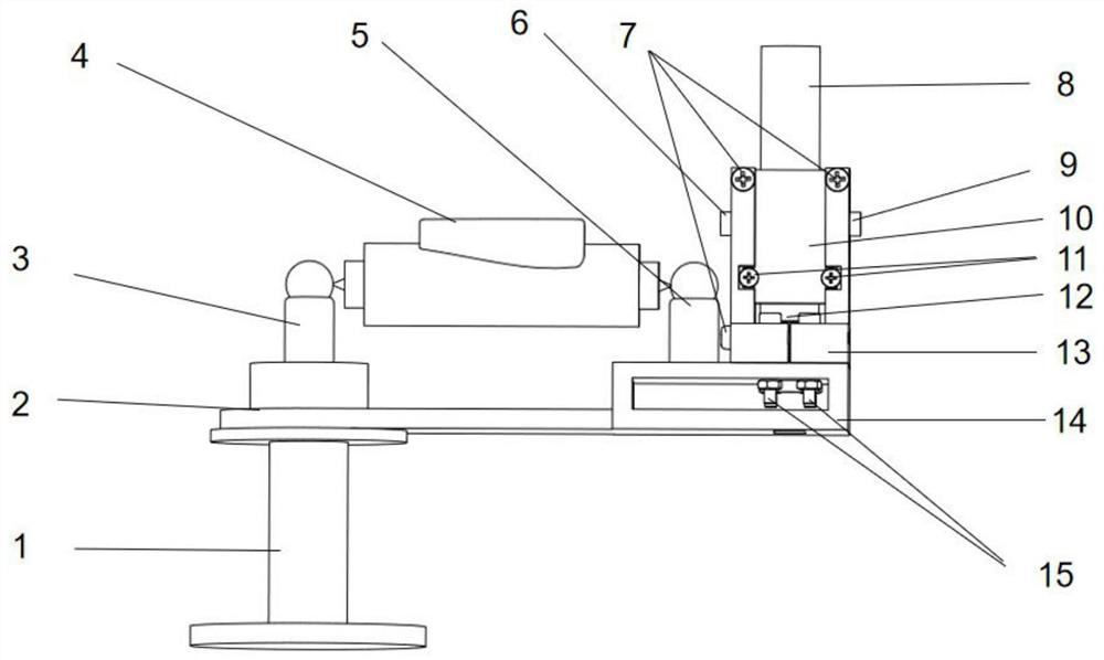
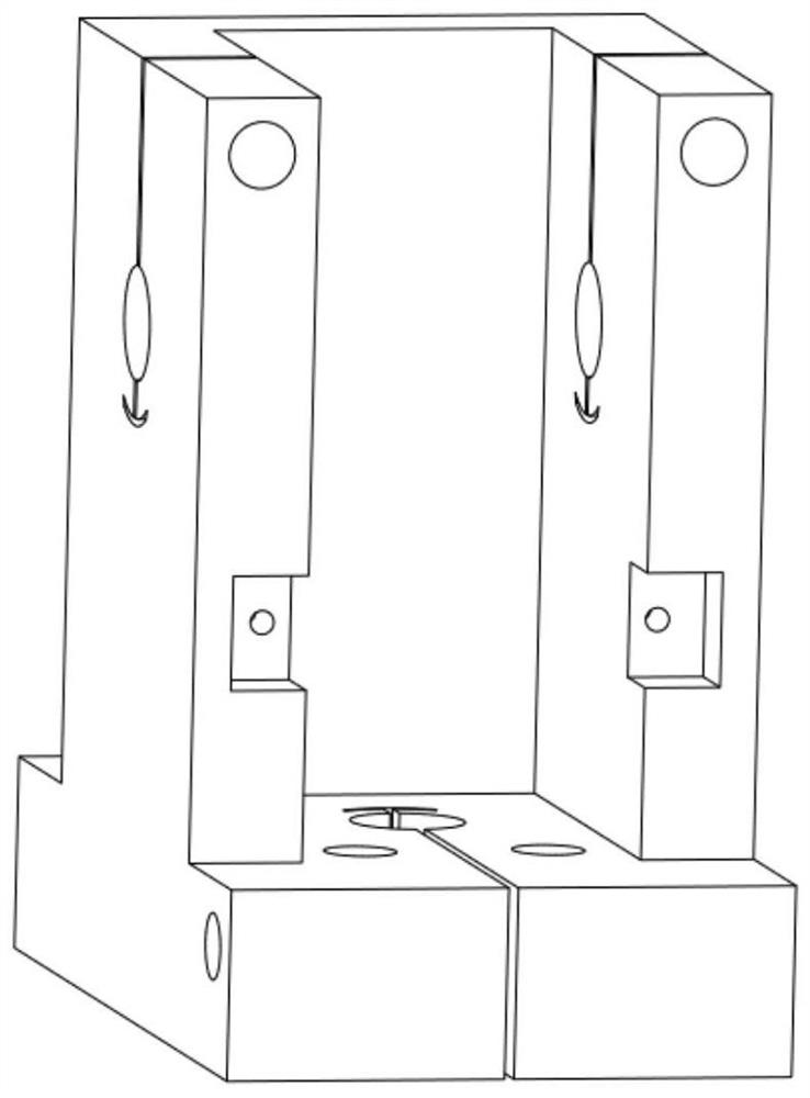
[0037] Such as figure 1 , 2 As shown in and 3, the method of measuring the three-dimensional error of the machine tool by combining the ballbar and the capacitive displacement sensor is as follows:

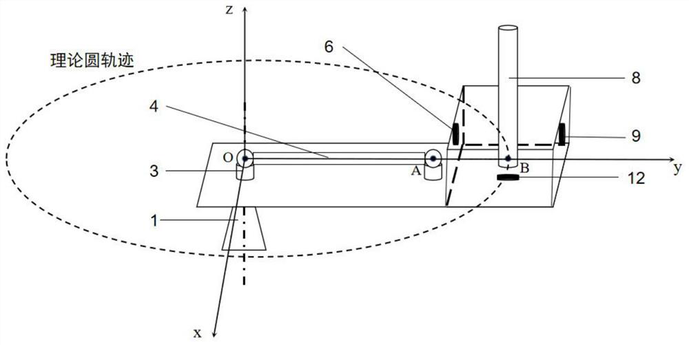
[0038] Step 1: Fix the base 1 on the machine tool table; one end of the synchronous rotary table 14 is supported on the base through the bearing 2; the ball seat 1 is fixed on the base 1, and the ball seat 2 5 is fixed on the synchronous rotary table On 14, guarantee the magnetic ball-and-socket ball center of ball seat one 3 and the magnetic ball-and-socket ball center of ball seat two 5 (as image 3 Shown at midpoint A) at the same height.

[0039] Step 2. Take the center of the magnetic ball-socket of ball seat 3 as the coordinate origin o. Initially, the line connecting the center of the magnetic ball-socket of ball seat 1 3 and ball seat 2 5 is the direction of the y-ax...


PUM


Abstract

The invention discloses a method for measuring three-dimensional errors of a machine tool through combination of a ball bar instrument and capacitance displacement sensors. The problem that the three-dimensional errors of machine tool main shaft motion are difficult to measure only by using the ball bar instrument is solved. The method comprises the steps that a base is fixed to a machine tool workbench; one end of a synchronous rotating table is supported on the base through a bearing; a first ball seat is fixed to the base, and a second ball seat is fixed to the synchronous rotating table; a clamp is fixed to the other end of the synchronous rotating table; the three capacitance displacement sensors are fixed to a machine tool main shaft through the clamp; the machine tool main shaft performs circular interpolation motion, the radial error and the axial error of the machine tool main shaft are measured through the three capacitance displacement sensors, the eccentric error of the synchronous rotating table is measured through the ball bar instrument, and the three-dimensional error of the main shaft is obtained through calculation. According to the method for measuring the three-dimensional errors of the machine tool through combination of the ball bar instrument and the capacitance displacement sensors, error measurement in the three-dimensional direction of the machine tool is realized, the measurement precision is high, and the error of the machine tool can be continuously measured within a certain radial range.

Description

technical field [0001] The invention belongs to the technical field of machine tool error detection, and in particular relates to a measurement method for measuring three-dimensional errors of machine tools by using a combination of a ballbar and a capacitance displacement sensor. Background technique [0002] With the continuous development of modern manufacturing industry, CNC machine tools have higher and higher requirements on the precision of machined parts. Effective detection and separation of various geometric errors of machine tools is the prerequisite for improving the machining accuracy of machine tools. Therefore, detecting machine tool errors quickly and accurately is the key to improving the machining accuracy of machine tools. Due to its high detection accuracy, low cost, high detection efficiency, easy installation, and convenient operation, the ballbar has become one of the most widely used instruments for the detection of geometric accuracy of CNC machine t...

Claims


Application Information

Patent Timeline
IPC IPC(8): B23Q17/00
CPCB23Q17/00
Inventor 王文许凯飞孙涛陈占锋王传勇卢科青
Owner HANGZHOU DIANZI UNIV
Why Eureka
Try Eureka