Integrated self interlocking mechanism with brake breaking function

A locking mechanism, integrated technology, applied in the direction of electromagnetic relay details, relays, electrical components, etc., can solve the problems of high cost, small space, user loss, etc., to achieve high product reliability, simple and compact structure, overall structure concise effect

Pending Publication Date: 2019-04-05
KUSN RUIPU ELECTRIC
View PDF0 Cites 6 Cited by
  • Summary
  • Abstract
  • Description
  • Claims
  • Application Information

AI Technical Summary

Problems solved by technology

Usually, the mechanical self-locking device and the electromagnet mechanism are separated and independent. The self-locking mechanism of the vacuum contactor with self-locking function in the existing market is relatively large, without stroke adjustment and opening and reset functions. These functions are completed by the electromagnet mechanism. As a result, the overall number of parts of the vacuum contactor is large, the cost is high, the layout mechanics is unbalanced, and the space is small, which is not conducive to assembly production and operation and maintenance
However, the opening and tripping coil cannot be energized for a long time, and it will often burn out and fail when the mechanism fails, and even cause electrical fires, bringing greater losses to users.

Method used


Image

  • Integrated self interlocking mechanism with brake breaking function
  • Integrated self interlocking mechanism with brake breaking function
  • Integrated self interlocking mechanism with brake breaking function

Examples


Embodiment Construction

[0026] A preferred embodiment of the present invention will be described in detail below in conjunction with the accompanying drawings. However, the scope of protection of the present invention is not limited to the following examples, that is, any simple equivalent changes and modifications made based on the patent scope of the present invention and the content of the description are still within the scope of the patent of the present invention.

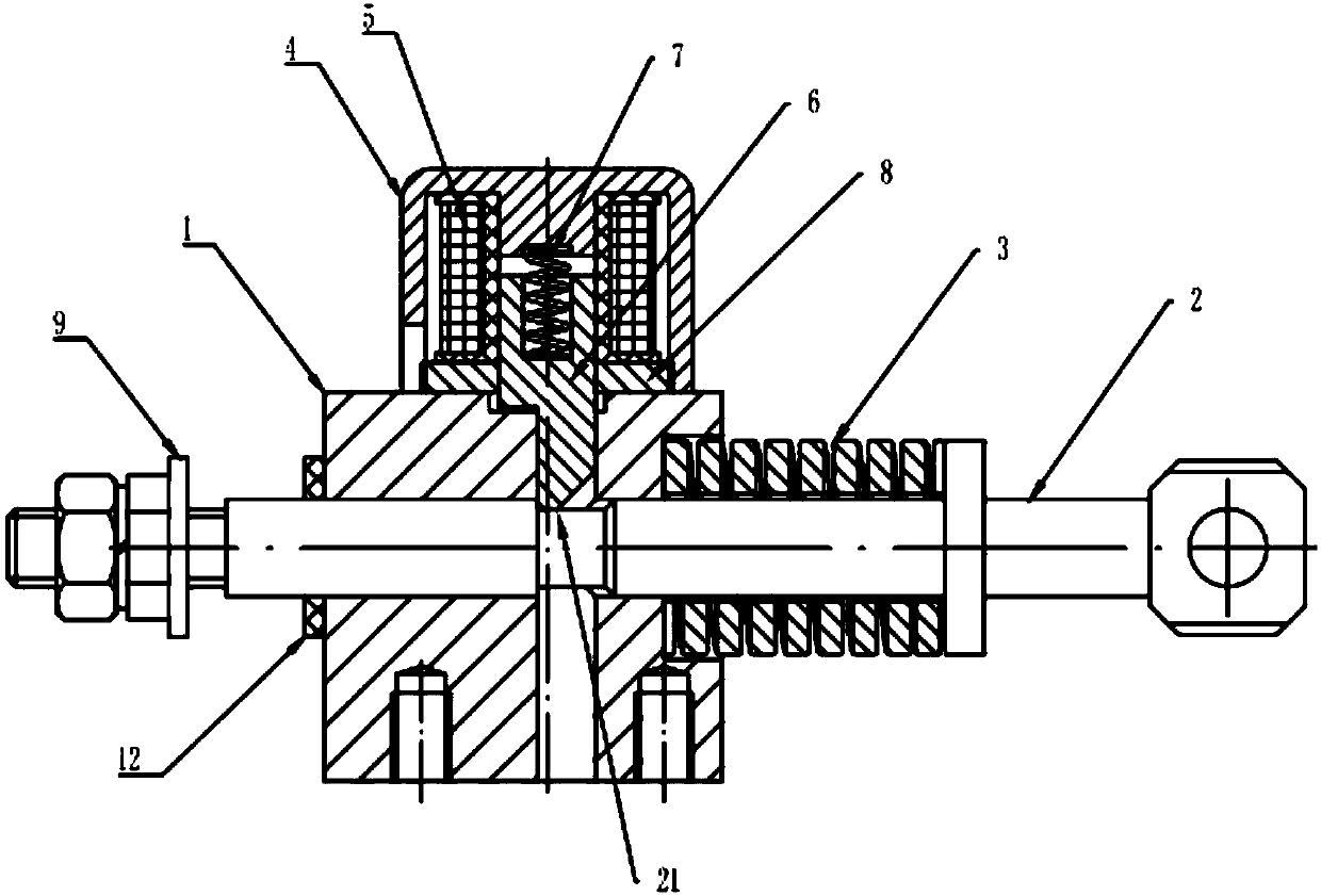
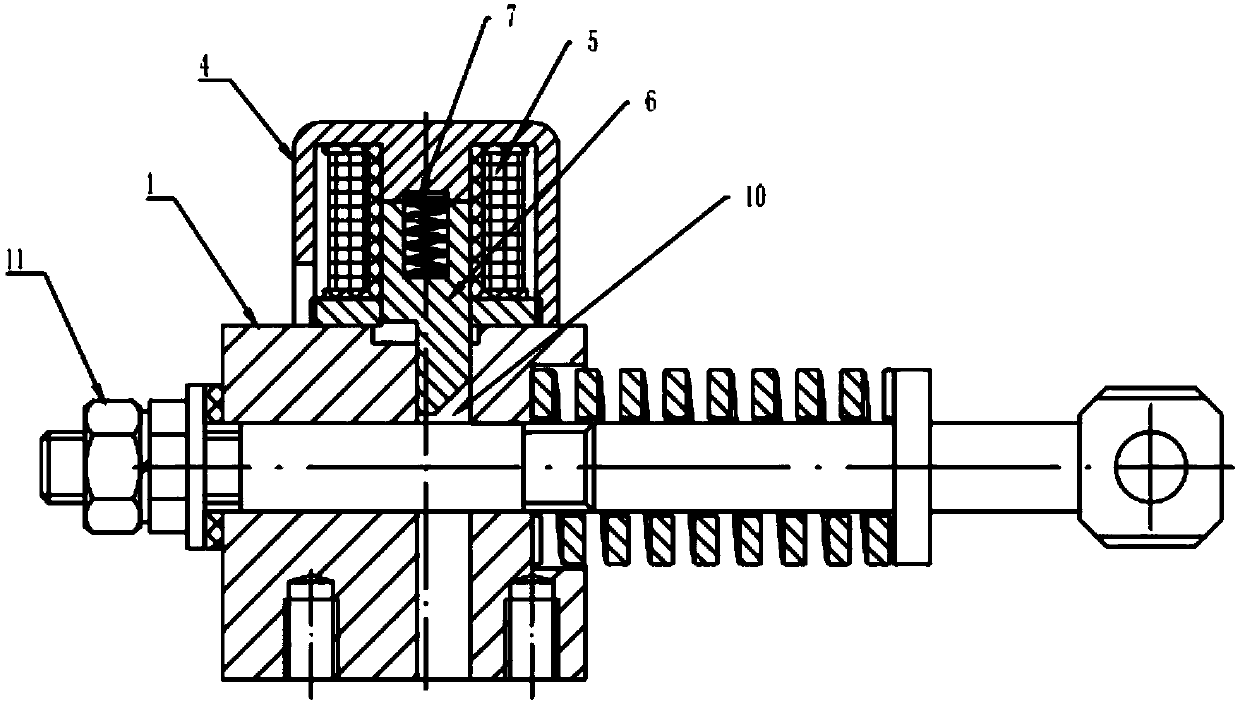
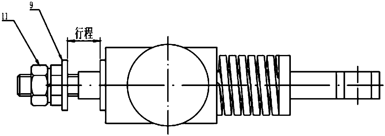
[0027] refer to Figure 1-3 , is an integrated self-locking mechanism with an opening function according to the present invention, including a base 1, a pull rod 2, an opening spring 3, a magnetic case 4, a tripping coil 5, a dead bolt 6, a return spring 7 and a yoke Iron 8.

[0028] The base 1 is provided with a longitudinal hole through the base along its longitudinal direction, and the middle part of the pull rod 2 is movably inserted in the longitudinal hole; the end of the pull rod 2 protruding from the base 1 is fixed with a ...


PUM


Abstract

The invention discloses an integrated self interlocking mechanism with a brake breaking function. The integrated self interlocking mechanism comprises a pedestal, a pull rod, a brake breaking spring,a magnetic shell, a tripping coil, a lock tongue, a reset spring and a yoke, a longitudinal hole penetrating the pedestal is formed in the pedestal, and the middle part of the pull rod movably penetrates the longitudinal hole; a limit block is fixed on one end, extending out the pedestal, of the pull rod, and the brake breaking spring sheathes the other end, extending out the pedestal, of the pullrod; the magnetic shell is fixed on one side surface of the pedestal; one end of the tripping coil is arranged at the bottom of the magnetic shell, the other end of the tripping coil clings one sidesurface of the yoke, and the other side surface of the yoke is fixed on the pedestal; a lock hole communicated with the longitudinal hole is formed in the yoke and the pedestal corresponding to the center of the tripping coil, one end of the lock tongue is placed at the center of the tripping coil, the other end of the lock tongue is placed in the lock hole, and the reset spring is located betweenthe lock tongue and the bottom of the magnetic shell; and an interlocking slot is formed in the periphery of the pull rod. The integrated self interlocking mechanism disclosed by the invention integrates three functions, namely a brake closing self interlocking function, a brake breaking driving function and a stroke adjusting function, into a whole, so that not only parts are reduced but also structure is simple and compact.

Description

technical field [0001] The invention belongs to the technical field of vacuum contactors, and in particular relates to an integrated self-locking mechanism with an opening function. Background technique [0002] At present, the control methods used by vacuum contactors mainly include electromagnetic holding and mechanical self-locking holding. Usually, the mechanical self-locking device and the electromagnet mechanism are separated and independent. The self-locking mechanism of the vacuum contactor with self-locking function in the existing market is relatively large, without stroke adjustment and opening and reset functions. These functions are completed by the electromagnet mechanism. As a result, the overall number of parts of the vacuum contactor is large, the cost is high, the layout mechanics is unbalanced, and the space is small, which is not conducive to assembly production and operation and maintenance. However, the opening and tripping coil cannot be energized for...

Claims


Application Information

Patent Timeline
Patent Type & Authority Applications(China)
IPC IPC(8): H01H9/20H01H50/32
CPCH01H9/20H01H50/32
Inventor 程肇平张立云
Owner KUSN RUIPU ELECTRIC
Why Eureka
Try Eureka