Side-hung auxiliary contact module with contact adhesion self-locking function

An auxiliary contact and self-locking technology, which is applied in the direction of electromagnetic relay details, relays, electrical components, etc., can solve the waste of resources, the failure to realize the locking of the moving contact at the normal end, and the contact cannot meet the application of mechanical interlocking contacts Demand and other issues to achieve the effect of ensuring safety, reducing burden and energy consumption

Pending Publication Date: 2019-04-05
XIAMEN HONGFA ELECTRICAL SAFETY & CONTROLS
View PDF0 Cites 2 Cited by
  • Summary
  • Abstract
  • Description
  • Claims
  • Application Information

AI Technical Summary

Problems solved by technology

[0002] There are mainly two types of side-mounted auxiliary contact module motion structures in the prior art. One type is that the motion direction of the auxiliary contact is consistent with the motion direction of the body contactor contact. Therefore, this type of side-mounted auxiliary contact module requires the body The contactor provides extra capacity to ensure the reliable operation of the auxiliary contact, and there is a waste of resources; the other type is that the direction of movement of the auxiliary contact is inconsistent with that of the main body contactor, but the reliable mechanical contact between the two contacts cannot be satisfied. Application requirements for interlocking contacts; when a contact adhesion fault occurs in the one-sided contact system, it is impossible to unconditionally lock the moving contacts at the normal end by physical means, and there is room for improvement in safety

Method used


Image

  • Side-hung auxiliary contact module with contact adhesion self-locking function
  • Side-hung auxiliary contact module with contact adhesion self-locking function
  • Side-hung auxiliary contact module with contact adhesion self-locking function

Examples


Embodiment 1

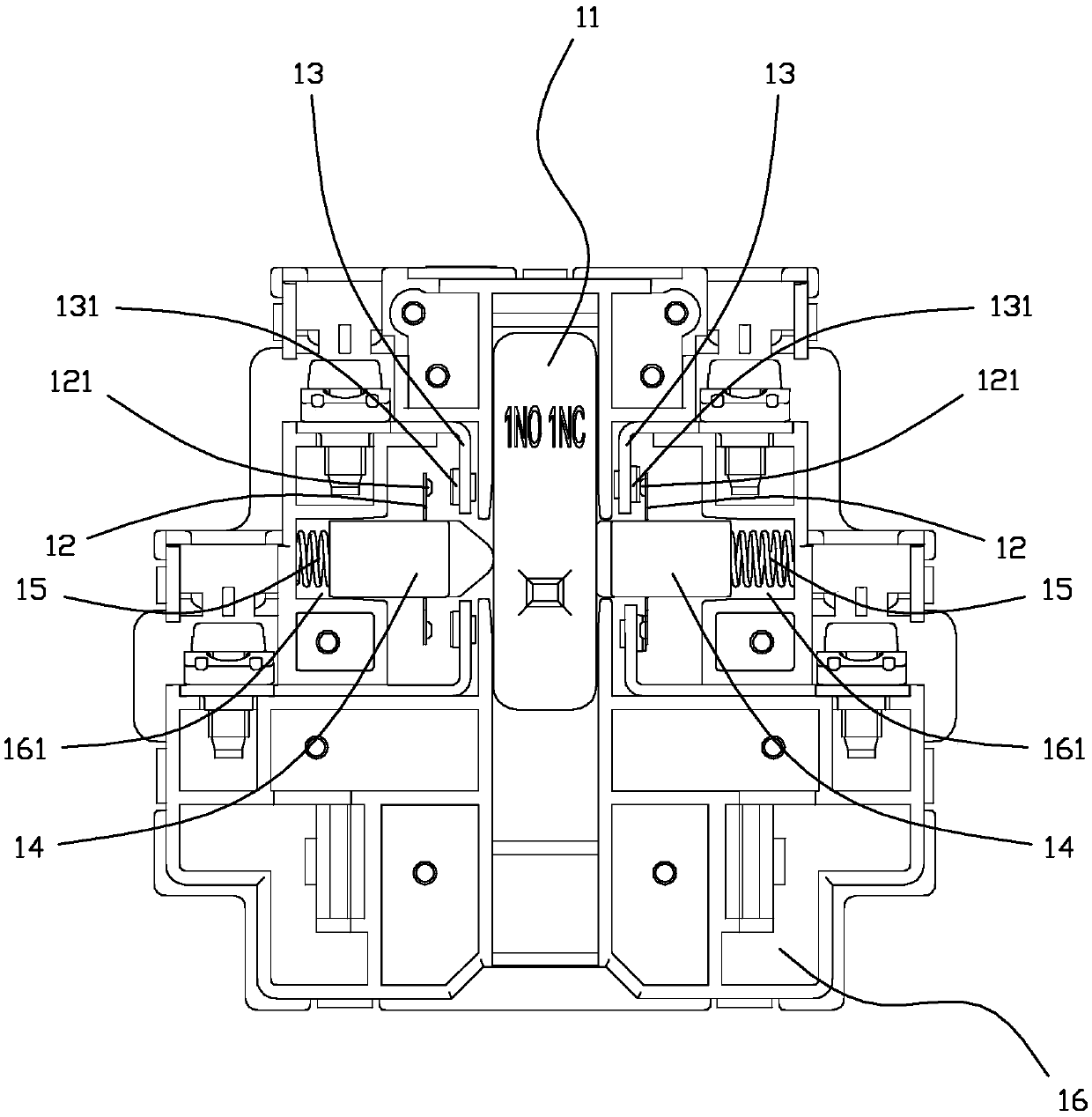
[0049] In this embodiment, the working states of the moving contacts 12 on both sides of the sliding bar 11 are mutually exclusive. Correspondingly, the specification of the sliding bar 11 is 1NO1NC, that is, NO+NC (normal open+normal close: normally open+normally closed). Such as image 3 , Figure 4 , Figure 5 , Figure 6 As shown, the moving contacts 12 on both sides of the sliding bar 11 are in the opposite working state at the same time under the action of the sliding bar 11; when the moving contact 12 on one side of the sliding bar 11 is closed with the static contact 13, the sliding bar The movable contact 12 on the other side of 11 is locked by the slide bar 11 and keeps disconnected from the static contact 13. Since the moving direction of the moving contact 12 is inconsistent with the moving direction of the body contactor 20, and through the mechanical action of the sliding rod 11, the moving contacts 12 on both sides of the sliding rod 11 form a mechanical inte...

Embodiment 2

[0061] In this embodiment, the moving contacts 12 on both sides of the sliding bar 11 work in the same state. Correspondingly, the specification of the sliding bar 11 is 2NO, that is, the initial working state of this embodiment is the auxiliary contact normally open. Such as Figure 11 , Figure 12 , Figure 13 , Figure 14 As shown, the moving contacts 12 on both sides of the sliding bar 11 are in the same working state at the same time under the action of the sliding bar 11; closed; or simultaneously drive the moving contacts 12 and the static contacts 13 on both sides to maintain the disconnected state.

[0062] Such as Figure 12 , Figure 14 , Figure 15 , Figure 16 As shown, the specific structure is as follows: the slide bar 11 is provided with a release section 114 and a locking section 115, the width of the release section 114 is smaller than that of the locking section 115, and they are arranged coaxially; the connection position between the release section ...

Embodiment 3

[0066] In this embodiment, the moving contacts 12 on both sides of the sliding bar 11 work in the same state. Correspondingly, the specification of the sliding bar 11 is 2NC, that is, the initial working state of this embodiment is that the auxiliary contact is normally closed. Such as Figure 17 , Figure 18 , Figure 19 , Figure 10 As shown, the moving contacts 12 on both sides of the sliding bar 11 are in the same working state at the same time under the action of the sliding bar 11; closed; or simultaneously drive the moving contacts 12 and the static contacts 13 on both sides to maintain the disconnected state.

[0067] Such as Figure 18 , Figure 20 , Figure 21 , Figure 22 As shown, the positions or directions of the release section 114 and the locking section 115 of this embodiment are opposite to those of the second embodiment, and furthermore, the only difference from the second embodiment is the initial working state.

[0068] Other parts are identical with...


PUM


Abstract

The invention relates to a side-hung auxiliary contact module with a contact adhesion self-locking function; through a sliding rod with a special structure, two sets of moving contacts form an associated mechanical interlocking relation; through the mechanical locking action of the sliding rods, when one set of contacts is closed, the other set of contacts is unconditionally kept open or the two sets of contacts are kept in an closed or disconnected state unconditionally. When a contact adhesion fault occurs on one of the contact systems on one side, and when the moving contact at the fault side cannot be driven by the sliding rod to change the working state, the sliding rod is locked, so that the contact support at the normal end is locked immovably by the sliding rod which is kept at thecurrent position, and therefore the safety is ensured. According to the module, no extra energy is needed for the body contactor basically, so that the state of the sliding rod can be kept, and the burden and energy consumption of the contactor are reduced. According to the module, the sliding rod and the movable contact and the contact support are all in linear motion, only needing to provide asmall movement space for the product, so that it is beneficial to miniaturization, lightening and thinning design of the product.

Description

technical field [0001] The invention relates to the technical field of contactors, in particular to a side-hanging auxiliary contact module with self-locking contacts. Background technique [0002] There are mainly two types of side-mounted auxiliary contact module motion structures in the prior art. One type is that the motion direction of the auxiliary contact is consistent with the motion direction of the body contactor contact. Therefore, this type of side-mounted auxiliary contact module requires the body The contactor provides extra capacity to ensure the reliable operation of the auxiliary contact, and there is a waste of resources; the other type is that the direction of movement of the auxiliary contact is inconsistent with that of the main body contactor, but the reliable mechanical contact between the two contacts cannot be satisfied. Application requirements for interlocking contacts; when a contact adhesion fault occurs in the one-sided contact system, it is imp...

Claims


Application Information

Patent Timeline
IPC IPC(8): H01H50/64H01H50/54
CPCH01H50/546H01H50/641
Inventor 刘长源张协利晏恒明
Owner XIAMEN HONGFA ELECTRICAL SAFETY & CONTROLS
Why Eureka
Try Eureka