Organic Light Emitting Diode Display with Narrow Bezel

A technology of light-emitting diodes and narrow borders, which is applied to semiconductor devices, electrical solid-state devices, electrical components, etc., can solve the problems of increasing the resistance value of the wires, unable to further reduce the spacing between the borders of the substrate and the frame, and decreasing the process yield.

Active Publication Date: 2020-11-03
RAYSTAR OPTRONICS
View PDF7 Cites 0 Cited by
  • Summary
  • Abstract
  • Description
  • Claims
  • Application Information

AI Technical Summary

Problems solved by technology

[0003] 1. Excessively reducing the line width of the wire will not only increase the resistance value of the wire itself, but also lead to the problem of a decrease in the process yield
[0004] 2. Excessively reducing the distance between two wires will increase the risk of short circuit between two adjacent wires
[0005] Therefore, just have another kind of wiring technology that vertically stacks by conducting wire to be proposed, as the disclosed a kind of display of Chinese Taiwan's new patent No. To the left and right sides adjacent to the effective display area, that is to say, the two sides of the substrate of the patent still have a certain width of the wiring area, and it is impossible to further reduce the outer frame of the substrate and the effective display area. The distance between the two makes the narrow frame development technology face another bottleneck

Method used


Image

  • Organic Light Emitting Diode Display with Narrow Bezel
  • Organic Light Emitting Diode Display with Narrow Bezel
  • Organic Light Emitting Diode Display with Narrow Bezel

Examples


Embodiment Construction

[0046] The present invention will be described in detail below with reference to the accompanying drawings and embodiments.

[0047] Before the present invention is described in detail, it should be noted that in the following description, similar components are designated by the same reference numerals. In addition, dimensions such as thickness and length shown in each drawing are different from the actual product.

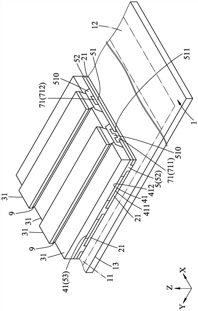
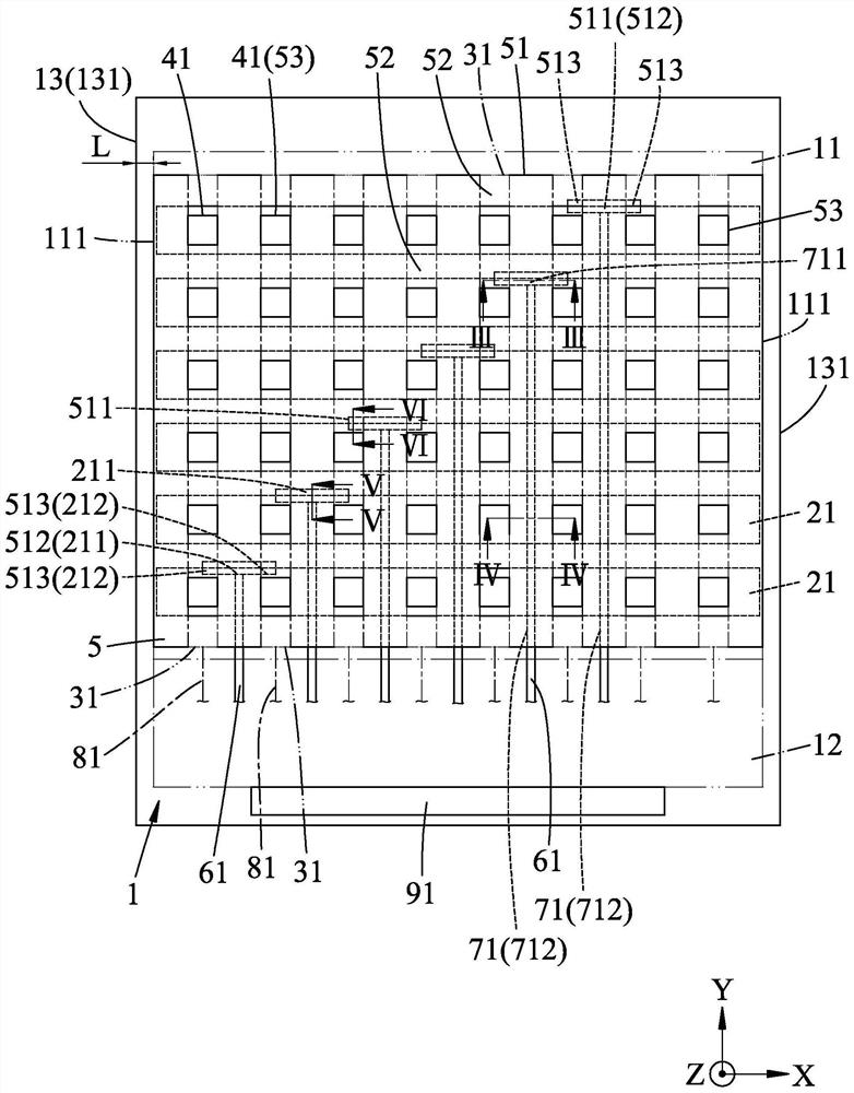
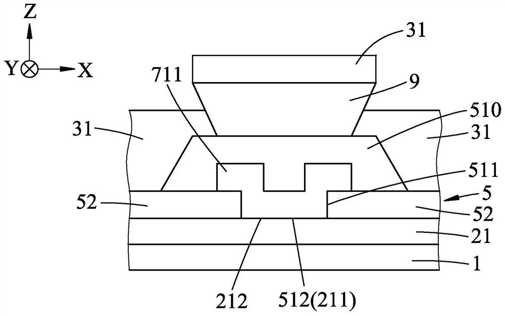
[0048] see figure 1 , 2 3. A first embodiment of the narrow-frame organic light emitting diode display of the present invention defines a first horizontal direction X, a second horizontal direction Y and a vertical direction Z that are orthogonal to each other. The narrow-frame OLED display includes a substrate 1, a plurality of first axial electrodes 21, a plurality of second axial electrodes 31, a plurality of organic light-emitting bodies 41, an insulating layer 5, and a plurality of first scanning wires 61. A plurality of bridge wires 71 , a plurality of s...


PUM


Abstract

An organic light emitting diode display with a narrow frame comprises a substrate having an effective display area and a routing area, a plurality of first axial electrodes and a plurality of second axial electrodes corresponding to the effective display area of ​​the substrate , a plurality of organic luminescent bodies, a layer of insulating layer, a plurality of bridging wires, and a plurality of first scanning wires and a plurality of second scanning wires located in the wiring area of ​​the substrate. In the present invention, each bridging wire is only routed through the lower side of the effective display area to extend to the routing area and is used to connect the respective first axial electrodes and the respective first scan wires, and each second scan wire The wires are routed on the lower side of the effective display area and connected to the respective second axial electrodes to improve the left and right sides of the existing display viewing surface. A certain width of the routing area still needs to be reserved and the routing cannot be reduced. The disadvantage of area, so it can indeed further achieve the purpose of reducing the width of the frame.

Description

technical field [0001] The present invention relates to a display, in particular to an organic light emitting diode display with a narrow frame. Background technique [0002] In the existing passive matrix OLED (Passive Matrix OLED, PMOLED for short), a plurality of anode scan signal lines (Segment scanline) and a plurality of cathode scan signal lines (Common scanline) are respectively along a first horizontal direction orthogonal to each other and a The second horizontal direction extends to the outside of an active display area, and is electrically connected to the driving IC through a plurality of contact nodes and a plurality of scanning signal lines located on the left and right sides of the active display area. In recent years, as the mainstream of display design is developing towards narrow border (Narrow Border), the existing methods to achieve narrow border by "reducing the line width of the wires" and "reducing the distance between two wires" have the following di...

Claims


Application Information

Patent Timeline
Patent Type & Authority Patents(China)
IPC IPC(8): H01L27/32
CPCH10K59/12H10K59/131
Inventor 廖育斌叶佩勋陈学文吴秉叡
Owner RAYSTAR OPTRONICS
Why Eureka
Try Eureka