
Battery module heating film, battery pack and lower housing thereof and battery pack assembling method

A battery module and heating film technology, applied in battery pack parts, batteries, secondary batteries, etc., can solve the problems of easy sticking, low assembly efficiency, and high foam prices, so as to improve the degree of fit and reduce The effect of production cost and scrap rate reduction

Active Publication Date: 2019-04-05
SVOLT ENERGY TECHNOLOGY CO LTD
View PDF15 Cites 5 Cited by
  • Summary
  • Abstract
  • Description
  • Claims
  • Application Information

AI Technical Summary

Problems solved by technology

Foam is a material with a certain compression and rebound ability. The greater the compression, the greater the rebound pressure it will provide, which will force the heating film to be in contact with the battery module. However, excessive compression will damage the battery. The shell under the package and the heating film bracket generate a huge force, causing its deformation to seriously affect the structural stability of the entire battery pack
The price of foam is high, and it cannot guarantee to maintain the initial physical properties in the case of long-term use. Once the foam cannot provide enough pressure, the degree of adhesion between the heating film and the battery module will be reduced, which will affect the heating film. Heating effect, but the compression is too small to ensure the bonding of the heating film and the battery module
[0004] The current technical solution is to paste the battery module and the heating film and then put them into the lower shell of the battery pack. This not only increases the labor intensity of the operator, but also tends to be stuck incorrectly, resulting in low assembly efficiency and causing damage to the heating film. The increase in scrap increases the cost of the entire R&D

Method used


Image

  • Battery module heating film, battery pack and lower housing thereof and battery pack assembling method
  • Battery module heating film, battery pack and lower housing thereof and battery pack assembling method

Examples


Embodiment Construction

[0028] It should be noted that, in the case of no conflict, the embodiments and features in the embodiments of the present invention can be combined with each other.

[0029] The present invention will be described in detail below with reference to the drawings and in combination with embodiments.

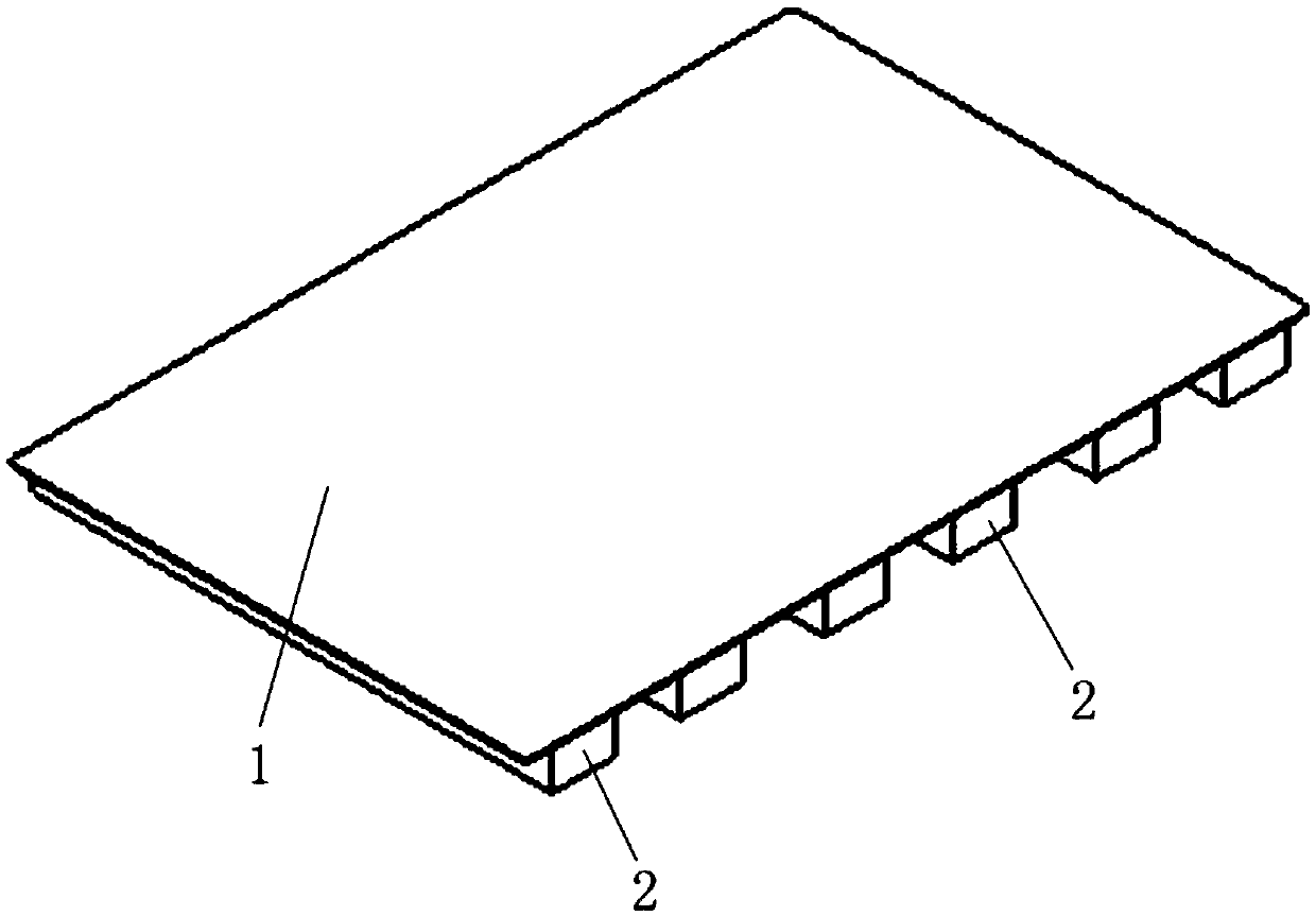
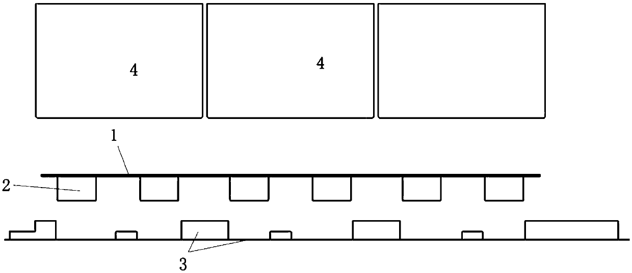
[0030] Such as figure 1 and figure 2 As shown in the structure, the battery module heating film of the present invention includes a film body 1, at least a part of the surface of the film body 1 facing the battery module is formed as a battery module heating area for contacting the battery module, Wherein, the heating area of ​​the battery module is covered with a thermally conductive adhesive layer (any existing thermally conductive adhesive, such as 3M adhesive can be used), and the thermally conductive adhesive layer is covered with a protective film that can be torn off.

[0031] In the battery module heating film, since the battery module heating area of ​​the battery modul...


PUM


Abstract

The present invention relates to the field of vehicle battery packs, and discloses a battery module heating film, a battery pack and a lower housing thereof, and a battery pack assembling method. Thebattery module heating film comprises a film body, a battery module heating area configured to be in contact with the battery module is formed at least one part, facing the surface of one side of thebattery module, of the film body, the battery module heating area is covered with a heat conductive adhesive glue layer, the heat conductive adhesive glue layer is coated with a protection film capable of tearing, in the actual usage, the battery module heating film is arranged at a corresponding area in the lower housing of the battery pack as required, the protection film is teared down, the battery module is assembled at the corresponding area of the lower housing of the battery pack and is bonded at the battery module heating film of the corresponding area so as to improve the applying degree of the battery module and the battery module heating film, improve the heating of the battery module and the over-temperature protection of the battery module heating film and obviously reduce therejection rate and the protection cost of the battery module heating film.

Description

technical field [0001] The invention relates to the technical field of vehicle battery packs, in particular to a battery module heating film, a battery pack lower case, a battery pack assembly method and a battery pack. Background technique [0002] With the improvement of people's quality of life, the penetration rate of vehicles is getting higher and higher. At the same time, with the improvement of environmental protection awareness, new energy vehicles such as hybrid vehicles and pure electric vehicles have been greatly developed. As the power source of new energy vehicles, the performance of power batteries is crucial to the cruising range and power performance of new energy vehicles. In order to improve the performance of electric vehicles and ensure the efficient heating performance of the battery when it works at low temperature, a heating film is usually installed between the battery module and the lower case. [0003] At present, the bonding between the heating fi...

Claims


Application Information

Patent Timeline
Patent Type & Authority Applications(China)
IPC IPC(8): H01M10/615H01M10/617H01M10/625H01M10/653H01M10/6571H01M2/10H01M10/04H01M50/204
CPCH01M10/04H01M10/615H01M10/617H01M10/625H01M10/653H01M10/6571H01M2220/20H01M50/20Y02E60/10Y02P70/50
Inventor 修书董杨振宇
Owner SVOLT ENERGY TECHNOLOGY CO LTD
Learn More