Self-lubricating pin contact

A pin contact and self-lubricating technology, applied in the direction of contact parts, can solve the problems of large insertion force and short insertion life, and achieve the goal of reducing insertion force, reducing insertion wear and improving insertion life Effect

Inactive Publication Date: 2019-04-05
HARBIN INST OF TECH +1
View PDF6 Cites 3 Cited by
  • Summary
  • Abstract
  • Description
  • Claims
  • Application Information

AI Technical Summary

Problems solved by technology

[0004] The purpose of the present invention is to provide a pin contact with self-lubricating function to solve the problems of short plug-in and pull-out life and large plug-in and pull-out force of rigid pin contacts in the prior art

Method used


Image

  • Self-lubricating pin contact
  • Self-lubricating pin contact
  • Self-lubricating pin contact

Examples


specific Embodiment approach 1

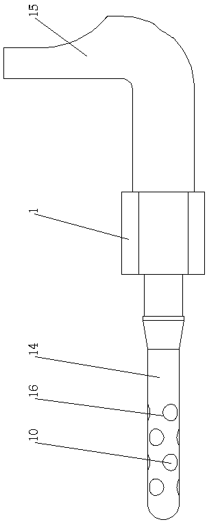
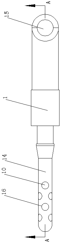
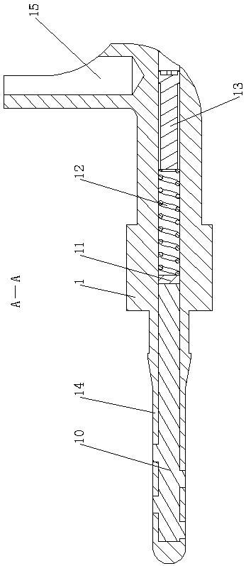
[0013] Specific implementation mode one: as Figure 1-Figure 3 As shown, this embodiment discloses a self-lubricating pin contact, including a pin contact body 1, and the self-lubricating pin contact also includes conductive grease 10 and a movable elastic limiter; the The pin contact body 1 is horizontally provided with a central hole from front to back, the central hole leads to the rear end of the pin contact body 1, the front end of the pin contact body 1 is closed, and the pin contact body 1 The front part is the plug-in end 14, and the side wall of the plug-in end 14 of the pin contact body 1 is provided with a plurality of holes 16 communicating with the center hole (preferably, the plurality of holes 16 are uniformly arranged on the plug-in On the side wall of the plug end 14 of the pin contact body 1), the center hole of the pin contact body 1 is located at the plug end 14 and filled with conductive grease 10, and the center hole of the pin contact body 1 is provided ...

specific Embodiment approach 2

[0014] Specific implementation mode two: as Figure 1-Figure 3 As shown, this embodiment is a further description of specific embodiment 1. The movable elastic limit device includes a piston 11, a piston spring 12 and a screw 13; the rear of the center hole of the pin contact body 1 There is a threaded hole at the end, the piston 11 is slidably arranged in the center hole of the pin contact body 1, and is in contact with the conductive grease 10, the screw 13 is screwed and connected with the threaded hole of the pin contact body 1, A piston spring 12 is arranged between the piston 11 and the screw 13 in the central hole of the pin contact body 1, and one end of the piston spring 12 is fixedly connected to the piston 11 (preferably, one end of the piston 11 and the piston spring 12 is welded as one).

specific Embodiment approach 3

[0015] Specific implementation mode three: as figure 1 , image 3 As shown, this embodiment is a further description of specific embodiment 1 or 2. The rear end of the pin contact body 1 is provided with a 90° bending end, and the 90° bending end is provided with a Pin solder cups 15 for wires (other termination methods, such as crimping, piercing, surface mount, fisheye, etc., can also be selected).


PUM


Abstract

A self-lubricating pin contact belongs to the technical field of electrical connectors. A self-lubricating pin contact of the present invention includes a pin contact body. The self-lubricating pin contact further includes a conductive grease and a movable elastic caging device. A central hole is horizontally disposed in the pin contact body from front to back, the central hole leads to a rear endof the pin contact body, a front end of the pin contact body is closed, the front end of the pin contact body is a plug end, a plurality of holes communicating with the central hole are disposed on asidewall of the plug end of the pin contact body, the central hole of the pin contact body is filled with the conductive grease at the plug end, the movable elastic caging device is disposed in the central hole of the pin contact body, and the movable elastic caging device can push the conductive grease to move toward the plug end. The present invention is applied to an electrical connector, so that a plugging and unplugging life of the contact of the electrical connector can be improved.

Description

technical field [0001] The invention belongs to the technical field of electrical connectors, in particular to a self-lubricating pin contact piece. Background technique [0002] In recent years, with the continuous improvement of the service life of the aerospace and aviation complete machine systems, the requirements for the plugging life of the electrical connector contacts are also continuously increasing. The main difficulty of plugging life is how to reduce wear while ensuring sufficient positive pressure, so as to slow down the increase of contact resistance and ensure the reliability of contact. [0003] The traditional contact parts have no lubrication function. In order to ensure the reliability of the contact, it is necessary to ensure that there is sufficient positive force between the contact pairs, and the positive force is proportional to the wear, which means that it is difficult to reduce the wear to ensure the reliability of the contact. The service life o...

Claims


Application Information

Patent Timeline
Patent Type & Authority Applications(China)
IPC IPC(8): H01R13/17H01R13/03
CPCH01R13/03H01R13/17
Inventor 朱宁徐乐翟国富
Owner HARBIN INST OF TECH
Why Eureka
Try Eureka