
Time synchronization method and device

A time synchronization and time stamp technology, applied in the field of navigation, can solve the problem of inability to accurately control the exposure time of the camera, and achieve the effect of accurate time stamp

Active Publication Date: 2021-03-05
IFLYTEK CO LTD
View PDF11 Cites 0 Cited by
  • Summary
  • Abstract
  • Description
  • Claims
  • Application Information

AI Technical Summary

Problems solved by technology

[0005] The present invention provides a time synchronization method and device to solve the problem in the related art that the exposure time of the camera cannot be precisely controlled

Method used


Image

  • Time synchronization method and device
  • Time synchronization method and device
  • Time synchronization method and device

Examples


Embodiment Construction

[0074] In order to make the above objects, features and advantages of the present invention more comprehensible, the present invention will be further described in detail below in conjunction with the accompanying drawings and specific embodiments.

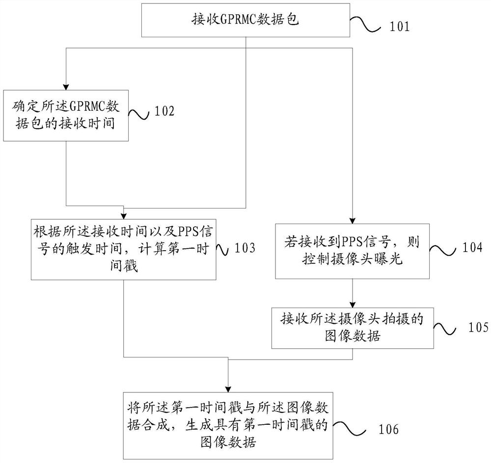
[0075] refer to figure 1 , shows a flow chart of the steps of an embodiment of a time synchronization method of the present invention, the method can be applied to a host, and specifically may include the following steps:

[0076] Step 101, receiving the GPRMC packet;

[0077] Among them, GPS (Global Positioning System, Global Positioning System) can send GPRMC (recommended positioning information) data packets to lidar;

[0078] The host in this embodiment of the present invention can receive the GPRMC data packet from the laser radar, or the host in the embodiment of the present invention can also receive the GPRMC data packet directly from the GPS.

[0079] The present invention does not specifically limit which object the GP...


PUM


Abstract

The invention provides a time synchronization method and device, the method comprising: receiving recommended positioning information GPRMC data packet; determining the receiving time of the GPRMC data packet; calculating the first timestamp according to the receiving time and the trigger time of the PPS signal; if receiving When the PPS signal is received, the exposure of the camera is controlled; the image data captured by the camera is received; the first time stamp is combined with the image data to generate image data with the first time stamp. After receiving the GPRMC data packet, the present invention can calculate the first time stamp according to the receiving time of the GPRMC data packet and the trigger time of the PPS signal, and utilize the PPS signal to control the exposure of the camera, and use the first time stamp as the exposure shot of the camera The time stamp information of the image, so that the time stamp of the captured image is the shooting time of the image, which realizes the precise control of the exposure time of the camera, and the captured image data has a precise time stamp.

Description

technical field [0001] The invention relates to the technical field of navigation, in particular to a time synchronization method and device. Background technique [0002] In the field of autonomous driving, Lidar and Camera are two common sensors. [0003] In autonomous driving technology, Lidar can scan obstacles by laser to generate point cloud data with time stamp. The camera can capture obstacles to generate images, and the embedded system of the vehicle can collect the image data captured by the camera and add time stamps to it. However, due to the poor real-time performance of the embedded system, it is difficult to achieve precise timing at the sub-millisecond level. Therefore, the time stamp added by the embedded system to the image data is not accurate enough, not the exact exposure time of the image by the Camera. [0004] Then there will be a time stamp error between the camera image data and the Lidar point cloud data, and the error will lead to errors in the ...

Claims


Application Information

Patent Timeline
Patent Type & Authority Patents(China)
IPC IPC(8): H04N5/235H04N5/06
CPCH04N5/06H04N23/73
Inventor 江涛陈赞羽
Owner IFLYTEK CO LTD
Learn More