A suction type pneumatic conveying equipment

A pneumatic conveying and equipment technology, which is applied in the field of suction pneumatic conveying equipment, can solve the problems such as inability to separate materials, achieve fast separation speed, complete separation effect, and increase separation effect

Active Publication Date: 2020-11-06
江苏道金智能制造科技股份有限公司
View PDF6 Cites 1 Cited by
  • Summary
  • Abstract
  • Description
  • Claims
  • Application Information

AI Technical Summary

Problems solved by technology

[0003] A suction-type pneumatic conveying equipment is set up to solve the above-mentioned background technology that needs to use two cyclone separators to separate twice to separate the material from the air flow, and the two cyclone separators still cannot separate the material from the air flow. The problem of complete separation of material from the gas stream

Method used


Image

  • A suction type pneumatic conveying equipment
  • A suction type pneumatic conveying equipment
  • A suction type pneumatic conveying equipment

Examples


Embodiment Construction

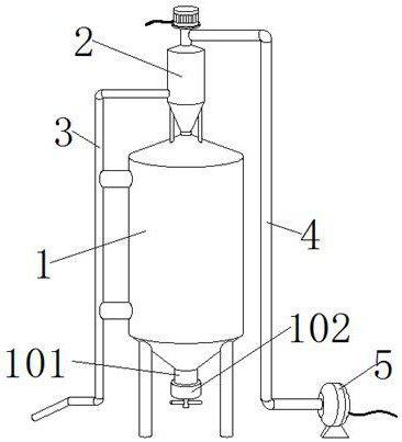
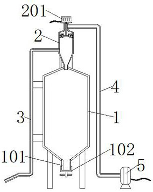
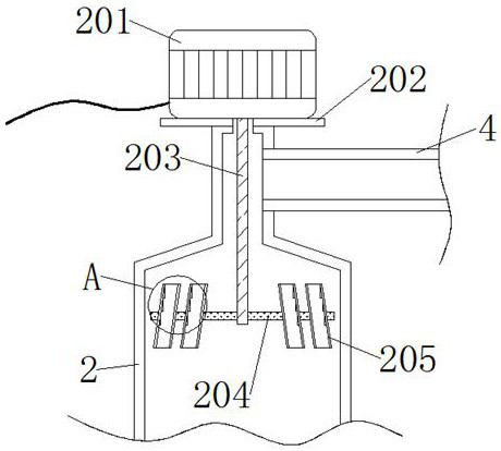
[0027] see Figures 1 to 8 Among them, in the embodiment of the present invention, a suction-type pneumatic conveying equipment includes a storage cylinder 1, a conveying pipe 3, an air pipe 4, a fan 5 and a separation cylinder 2. The top of the storage cylinder 1 is embedded with a separation cylinder 2, and the separation cylinder One side of the 2 is embedded and welded with a conveying pipe 3, and the other side of the conveying pipe 3 is embedded and welded with an air pipe 4. One end of the air pipe 4 is embedded and welded in the fan 5, and the bottom of the storage cylinder 1 is embedded and welded with a discharge pipe 101. The bottom of the pipe 101 is threaded with a threaded cover 102, and one side of the delivery pipe 3 is welded with the storage cylinder 1 through a pole; Strut 2010, bearing 2011, rotating bolt 2012, fixed rod 2013, curved surface playing plate 2014, bump 2015, curved plate 208 and rubber strip 209, the top welding of separating cylinder 2 is pro...


PUM


Abstract

The invention provides suction type pneumatic conveying equipment. The suction type pneumatic conveying equipment comprises a storage cylinder, a conveying pipe, a gas pipe, a fan and a separating cylinder; the separating cylinder is embedded and welded in the top of the storage cylinder; the conveying pipe is embedded and welded in one side of the separating cylinder; the gas pipe is embedded andwelded in the other side of the conveying pipe; one end of the gas pipe is embedded and welded in the fan; a discharge pipe is embedded and welded in the bottom of the storage cylinder; the bottom ofthe discharge pipe is sleeved with a screw cap in a threaded mode; one side of the conveying pipe is welded to the storage cylinder through a support rod; a carrier plate is welded to the top of theseparating cylinder; and a motor is welded to the top of the carrier plate. A separating pipe is driven by a disc to rotate at a high speed, in the movement process of the separating pipe, due to rotation of the separating pipe, the separating pipe can lay down materials in the separating pipe before the materials fall off from the separating pipe, so that the materials fall into the separating cylinder, the materials are completely separated from airflow, and thus the materials can be completely separated from airflow just through one time of separating.

Description

technical field [0001] The invention relates to the technical field of pneumatic conveying, in particular to a suction-type pneumatic conveying device. Background technique [0002] Pneumatic conveying, also known as suction-type pneumatic conveying, uses the energy of airflow to convey granular materials along the direction of airflow in a closed pipeline. It is a specific application of fluidization technology. The pneumatic conveying device has a simple structure and is easy to operate. It can be used for horizontal, vertical or inclined conveying. During the conveying process, it can also perform physical operations such as heating, cooling, drying and air classification of materials or certain chemical operations. At present, there are many ways of pneumatic conveying, which can be roughly divided into three types: suction-type pneumatic conveying, pressure-feeding pneumatic conveying and hybrid pneumatic conveying, while suction-type pneumatic conveying equipment needs...

Claims


Application Information

Patent Timeline
Patent Type & Authority Patents(China)
IPC IPC(8): B65G53/60B65G53/34
CPCB65G53/34B65G53/60
Inventor 范永明赵先孙威杨晓双
Owner 江苏道金智能制造科技股份有限公司
Why Eureka
Try Eureka