Steel tempering equipment

A technology of steel and equipment, applied in the field of steel tempering equipment, can solve the problems of low efficiency, poor steel quality, uneven addition of coolant, etc., and achieve the effect of reasonable structure

Inactive Publication Date: 2019-04-09
海盐县秦山镇秦丰编织袋厂
4 Cites 0 Cited by

AI-Extracted Technical Summary

Problems solved by technology

[0003] The purpose of the present invention is to overcome the shortcomings of the above-mentioned prior art and provide a steel tempering equipment, which aims to solve the steel tempering proces...

Abstract

The invention discloses steel tempering equipment. The steel tempering equipment is characterized by comprising a machine body housing, a reaction furnace, a rotary main shaft, connection shafts, a support frame and a power motor, wherein the reaction furnace is arranged in the machine body housing; the rotary main shaft is arranged at the center in the reaction furnace; the connection shafts arearranged at the two ends of the rotary main shaft; the support frame is arranged at ends away from the rotary main shaft, of the connection shafts; the power motor is arranged in the support frame; and the power motor is connected with the connection shafts. Compared with the prior art, the steel tempering equipment is reasonable in structure; through arrangement for a console, a temperature in the reaction furnace can be automatically controlled; and a cooling liquid enters the rotary main shaft through the connection shafts, and then is uniformly injected from holes in the rotary main hole,so that the technical problems of low efficiency caused due to the need of manual detection control in temperature control, low steel quality caused due to non-uniform adding for the cooling liquid, in a steel tempering process in the prior art, are solved.

Application Domain

Heat treatment process control

Technology Topic

Automatic controlSteel quality +2

Image

  • Steel tempering equipment
  • Steel tempering equipment

Examples

  • Experimental program(1)

Example Embodiment

[0016] In order to make the object, technical solution and advantages of the present invention clearer, the present invention will be further described in detail below with reference to the accompanying drawings and embodiments. However, it should be understood that the specific embodiments described here are only used to explain the present invention, and are not intended to limit the scope of the present invention. Also, in the following description, descriptions of well-known structures and techniques are omitted to avoid unnecessarily obscuring the concept of the present invention.
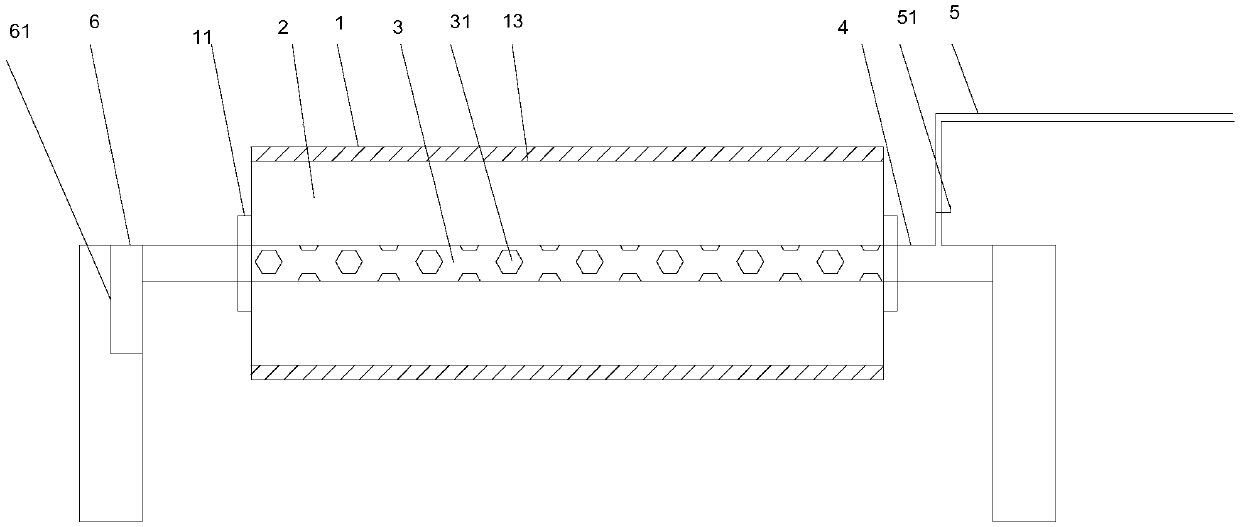
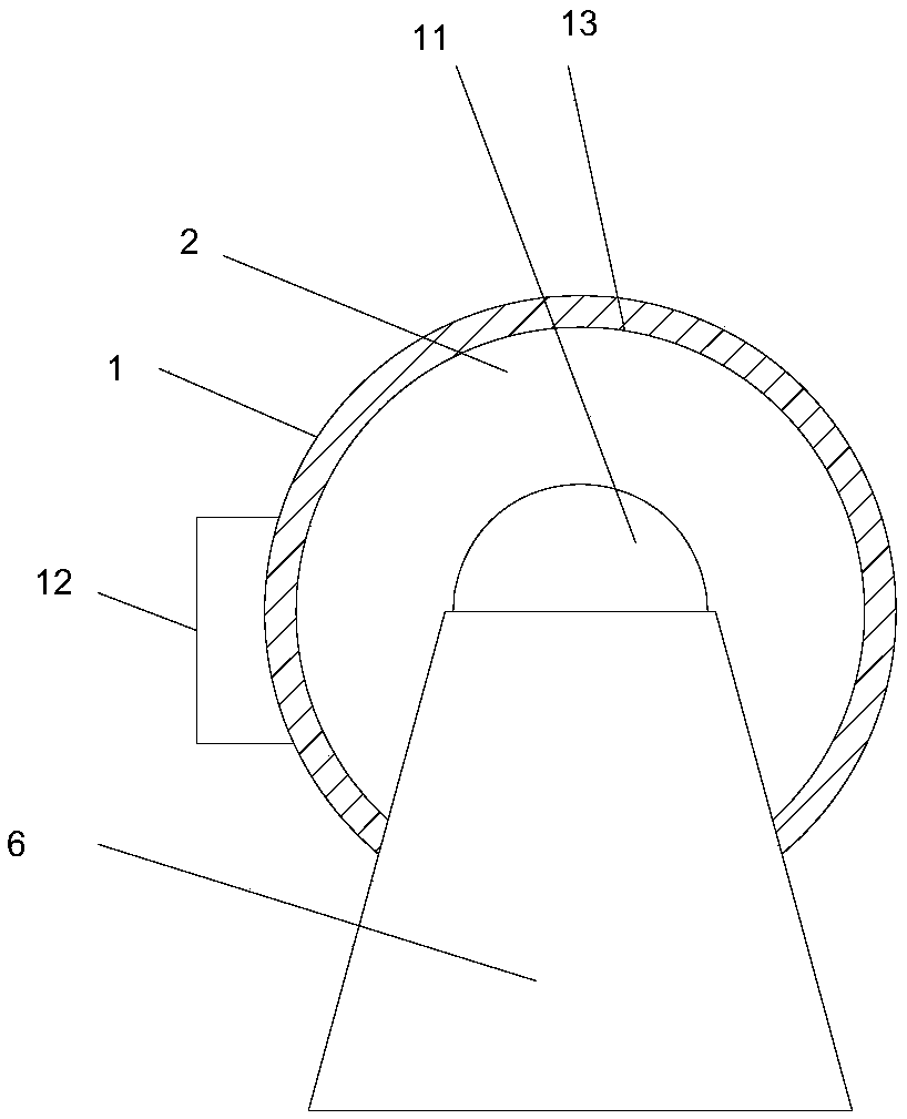
[0017] refer to figure 1 and figure 2 , the embodiment of the present invention provides a steel tempering equipment, which is characterized in that it includes a body shell 1, a reaction furnace 2, a rotating spindle 3, a connecting shaft 4, a support frame 6 and a power motor 61, and the body shell 1 is equipped with A reaction furnace 2, the center of the reaction furnace 2 is provided with a rotating main shaft 3, the two ends of the rotating main shaft 3 are provided with a connecting shaft 4, and the end of the connecting shaft 4 away from the rotating main shaft 3 is provided with a support frame 6, the A power motor 61 is arranged inside the support frame 6 , and the power motor 61 is connected with the connecting shaft 4 .
[0018] The connecting shaft 4 is provided with an infusion tube 5 for transporting cooling liquid, and the infusion tube 5 is provided with a control valve 51 , and the other end of the infusion tube 5 is connected to a cooling liquid container. Both the connecting main shaft 3 and the connecting shaft 4 are hollow structures, the connecting main shaft 3 and the connecting shaft 4 are of an integrated structure, and the outer surface of the connecting main shaft 3 is provided with several holes 31 for cooling liquid to flow out. 31 are equally spaced.
[0019] The two ends of the body shell 1 are provided with a door 11 for the steel material to enter and exit, and the door 11 is directly connected with the two ends of the reaction furnace 2 . A console 12 is provided on the outside of the body shell 1, and a motor for controlling the temperature of the reaction furnace is provided inside the console 12. The body shell 1 has a cylindrical structure, and the body shell 1 is made of a material with high temperature resistance and good heat insulation performance. The reaction furnace 2 has a cylindrical structure, and the two reaction furnaces are made of high temperature resistant materials. A heat insulating layer 13 is provided between the body shell 1 and the reaction furnace 2 .
[0020] Working process of the present invention:
[0021] During the working process of the steel tempering equipment of the present invention, the steel is put into the reaction furnace 2 from the door 11, the door 11 is closed, the power motor 61 is turned on, and the temperature on the console 12 is set so that the steel is kept at a constant temperature. When it is necessary to lower the temperature and cool down, open the control valve 51 of the infusion pipe 5, the coolant flows into the rotating spindle 3 from the connecting shaft 4, and sprays out from the hole 31 on the rotating spindle 3, so that the surface of the steel can be uniform cool down.

PUM

no PUM

Description & Claims & Application Information

We can also present the details of the Description, Claims and Application information to help users get a comprehensive understanding of the technical details of the patent, such as background art, summary of invention, brief description of drawings, description of embodiments, and other original content. On the other hand, users can also determine the specific scope of protection of the technology through the list of claims; as well as understand the changes in the life cycle of the technology with the presentation of the patent timeline. Login to view more.

Similar technology patents

High capacity three-dimensional parking garage

Owner:QUZHOU LECHUANG ENERGY SAVING TECH

Double-mould turnover casting machine for casting piston

Owner:SHIJIAZHUANG JINGANG KAIYUAN POWER SCI & TECH

Bearing outer ring cleaning device

ActiveCN106583286AReasonable structureclean well
Owner:安徽千禧精密轴承制造有限公司

Classification and recommendation of technical efficacy words

Why Eureka
Try Eureka