Prefabricated integral reinforced concrete frame-brace composite shear wall structure

A technology of reinforced concrete frame and shear wall, which is applied to walls, building components, building structures, etc., can solve the problems of cumbersome and inconvenient assembly, difficult assembly, and affecting the normal use of frame-supported composite shear wall structures.

Inactive Publication Date: 2019-04-09
卓勇
View PDF0 Cites 1 Cited by
  • Summary
  • Abstract
  • Description
  • Claims
  • Application Information

AI Technical Summary

Problems solved by technology

[0005] Aiming at the deficiencies of the prior art, the present invention provides an assembled integrated reinforced concrete frame-stayed composite shear wall structure, which can effectively assemble the frame-stayed composite shear wall structure, and can effectively prevent the frame-stayed composite shear wall structure from The force wall structure has the advantages of local buckling when the lateral force is small, and solves the need to measure the size of the room on site when assembling the integral reinforced concrete frame-stayed composite shear wall structure. Assemble the frame-stayed composite shear wall structure, and finally cast reinforced concrete. During assembly, it is necessary to carry a large number of tools to process it to meet the size of the room. It is not easy to assemble it, and it is too It is cumbersome and inconvenient, and in addition to the horizontal force generated by the external load, the frame also bears the additional horizontal force to pull back the shear force. The frame-braced composite shear wall structure will buckle locally when the lateral force is small, thus affecting the frame. Problems in normal use of braced composite shear wall structures

Method used


Image

  • Prefabricated integral reinforced concrete frame-brace composite shear wall structure
  • Prefabricated integral reinforced concrete frame-brace composite shear wall structure
  • Prefabricated integral reinforced concrete frame-brace composite shear wall structure

Examples


Embodiment Construction

[0024] The following will clearly and completely describe the technical solutions in the embodiments of the present invention with reference to the accompanying drawings in the embodiments of the present invention. Obviously, the described embodiments are only some, not all, embodiments of the present invention. Based on the embodiments of the present invention, all other embodiments obtained by persons of ordinary skill in the art without making creative efforts belong to the protection scope of the present invention.

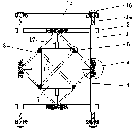
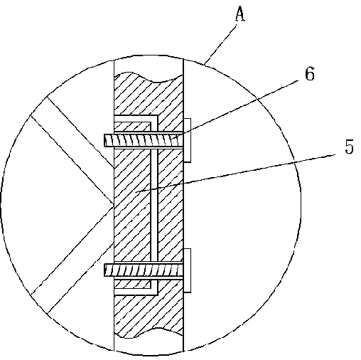
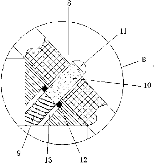
[0025] see Figure 1-4, an assembled integral reinforced concrete frame braced composite shear wall structure, comprising two parallel first frame beams 1 and two parallel second frame beams 2, the upper and lower sides of the two first frame beams 1 are provided with There is a second threaded hole, and the second threaded hole is internally threaded with threaded rods 14, and the outer walls of multiple threaded rods 14 are fixedly connected with rotating bl...


PUM


Abstract

The invention relates to the field of building technology, and discloses a prefabricated integral reinforced concrete frame-brace composite shear wall structure which comprises two parallel first frame beams and two parallel second frame beams, wherein the two first frame beams and the two second frame beams are fixed perpendicularly to each other; the first frame beams and the second frame beamsare internally provided with a reinforcing mechanism; the reinforcing mechanism comprises four first reinforcing bars; the four first reinforcing bars are distributed in a diamond shape; every two adjacent ends of every two adjacent first reinforcing rods are fixedly connected with a fixing block jointly; and first grooves corresponding to the fixing blocks are formed in the ends, close to the first reinforcing rods, of the first frame beams and the second frame beams. According to the prefabricated integral reinforced concrete frame-brace composite shear wall structure, a frame-brace composite shear wall structure can be effectively prefabricated, and the frame-brace composite shear wall structure can be effectively prevented from locally buckling when the lateral force is relatively small.

Description

technical field [0001] The invention relates to the technical field of buildings, in particular to an assembled integral reinforced concrete frame-braced composite shear wall structure. Background technique [0002] The shear wall structure uses reinforced concrete wall panels to replace the beams and columns in the frame structure, which can bear the internal forces caused by various loads and can effectively control the horizontal force of the structure. The structure of the force is called the shear wall structure. This structure is widely used in high-rise buildings. The shear wall structure refers to the structure in which the main load-bearing structures in the vertical and horizontal directions are all structural walls. When the walls are properly positioned in the building, they form a structural system that effectively resists horizontal action and, at the same time, acts as a partition of space. The height of the structural wall is generally equal to the height o...

Claims


Application Information

Patent Timeline
Patent Type & Authority Applications(China)
IPC IPC(8): E04B2/56
CPCE04B2/56
Inventor 卓勇
Owner 卓勇
Why Eureka
Try Eureka