Fan system and range hood using same

A technology for a fan system and a range hood, which is applied in the field of kitchen appliances, can solve the problems that the height of the cabinet exceeds the floor limit, cannot be used normally, and the volume of the centrifugal fan is large, and achieves the effect of small size, small size, and compact fan structure.

Pending Publication Date: 2019-04-09
NINGBO FOTILE KITCHEN WARE CO LTD
View PDF4 Cites 1 Cited by
  • Summary
  • Abstract
  • Description
  • Claims
  • Application Information

AI Technical Summary

Problems solved by technology

Due to the large size of the centrifugal fan, when two centrifugal fans are arranged in series as mentioned above, the height of the casing will exceed the limit of the floor, so that it cannot be used normally

Method used


Image

  • Fan system and range hood using same
  • Fan system and range hood using same
  • Fan system and range hood using same

Examples


Embodiment 1

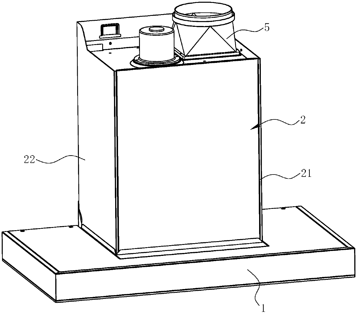
[0030] See Figure 1 ~ Figure 3 , A range hood, comprising a smoke collecting hood 1, a chassis 2 located above the smoke collecting hood 1. For ease of description, in the following, "front", "rear", "left", "right", "up", "Down" refers to the position of the range hood relative to the user when the user uses the range hood, and does not limit the structure.

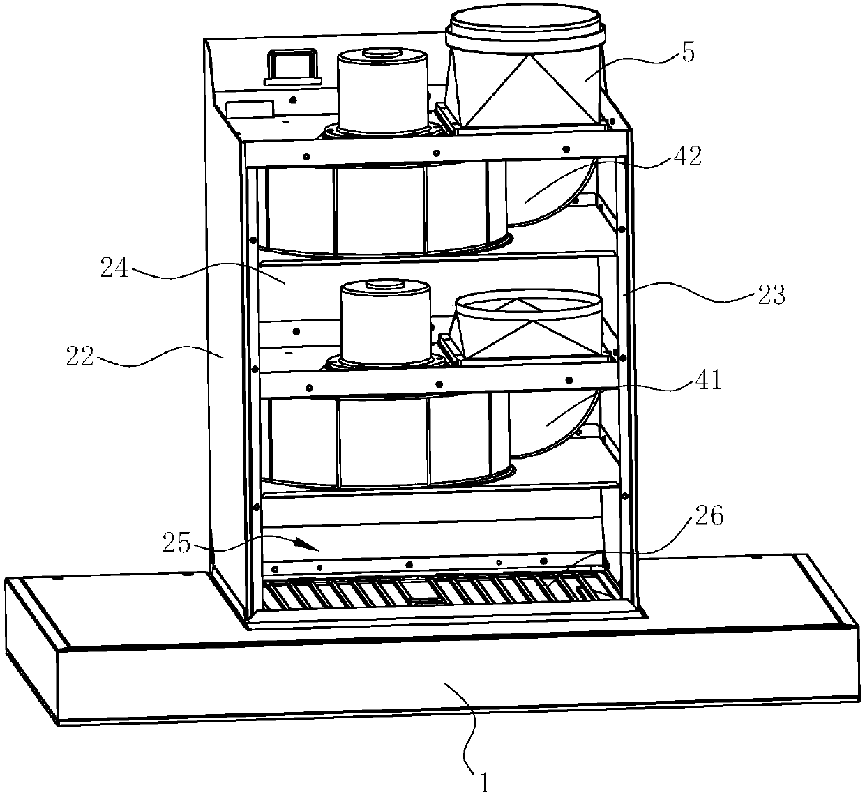
[0031] In this embodiment, the chassis 2 includes a front side wall 21, a left side wall 22 and a right side wall 23 located on the left and right sides, and a rear side wall 24. The aforementioned front side wall 21, left side wall 22, and right side wall A cavity is enclosed between 23 and the rear side wall 24. The cavity is the air duct 25 in the case 2. The entrance of the air duct 25 (the bottom end of the case 2) and the air inlet (not (Shown) Correspondingly, a rectifying net 26 is provided at the entrance of the air duct 25. A fan system 4 is provided in the chassis 2 and the fan system 4 includes two independen...

Embodiment 2

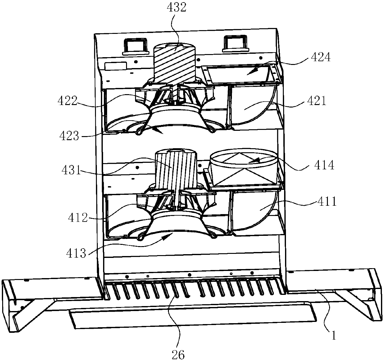
[0039] See Figure 4 with Figure 5 In this embodiment, the difference from the third embodiment above is that the first ternary fan 41 (as the first-stage fan) and the second ternary fan 42 (as the second-stage fan) are arranged in a staggered manner, that is, the The first volute 411 and the second volute 412 are in opposite directions, the first air inlet 413 of the first ternary fan 41 is close to the right, and the second air inlet 423 of the second ternary fan 42 is close to the left. The second air outlet 414 of the fan 41 is close to the left, and the second air outlet 424 of the second ternary fan 42 is close to the right. At this time, the first air outlet 414 of the first ternary fan 41 and the second ternary fan 42 The second air inlet 423 corresponds or nearly corresponds in the vertical direction. The distance between the first air inlet 413 and the second air inlet 423 is the distance in the vertical direction.

Embodiment 3

[0041] See Image 6 with Figure 7 In this embodiment, the difference from the third embodiment above is that the first three-element fan 41 and the second three-element fan 42 are arranged obliquely up and down respectively, that is, the first intake of the first three-element fan 41 The air inlet 413 faces downward obliquely from the horizontal direction, and the second air inlet 423 of the second three-element fan 42 faces downward obliquely from the horizontal direction.

[0042] The first air outlet 414 of the first ternary fan 41 and the second air inlet 423 of the second ternary fan 42 are connected by a duct 46. The vertical distance between the center of the first air inlet 413 of the first ternary fan 41 and the inlet of the air duct 25 is 0.5 to 2 times the diameter of the first ternary impeller 412.

[0043] This kind of oblique series connection has a lower overall height and a higher static pressure at the outlet of the fan, which is beneficial to overcome the resista...


PUM


Abstract

The invention discloses a fan system. The fan system comprises two fans, and is characterized in that the two fans are a first three-dimensional fan and a second three-dimensional fan separately; thefirst three-dimensional fan comprises a first three-dimensional impeller and a first air inlet port; the second three-dimensional fan comprises a second three-dimensional impeller and a second air inlet port; in a lampblack flowing path, the second air inlet port is located in the downstream part of the first air inlet port; and the orientations of the first air inlet port and the second air inletport are the same. The invention further discloses a range hood using the fan system. The two three-dimensional fans are adopted, and each fan is compact in structure, relatively small in dimension,high in efficiency and air pressure, large in generated negative pressure gradient, and capable of greatly increasing lampblack absorption efficiency; and through the small-dimension three-dimensionalfans, the two three-dimensional fans still have small dimensions under a series combined manner, so that the existing dimensions of the range hood do not need to be changed, and installation is alsonot limited by the floor height of floors.

Description

Technical field [0001] The invention relates to kitchen appliances, especially a fan system, and a range hood using the fan system. Background technique [0002] Range hoods have become one of the indispensable kitchen appliances in modern households. Generally, range hoods include top-suction type and near-suction type. The top-suction type range hood uses the principle of rising heat to absorb and discharge the naturally rising oil fume generated during cooking. In addition, it is clean and light, and takes up less space. It has more and more widespread applications, but because its power source is far away from the stove, the suction effect of the power source is reduced, and the oil fume can not be completely cleaned; the near suction type range hood uses the vortex wind pressure to move away The cooking fume near the stove is absorbed in an arc, which can reduce the adverse effects on human health, and the power source is closer to the stove, which basically does not reduce...

Claims


Application Information

Patent Timeline
Patent Type & Authority Applications(China)
IPC IPC(8): F24C15/20
CPCF24C15/20
Inventor 梁雪斐周佳杰刘逸茅忠群诸永定刘戈
Owner NINGBO FOTILE KITCHEN WARE CO LTD
Why Eureka
Try Eureka