piezoresistive accelerometer

An acceleration sensor, piezoresistive technology, applied in the direction of acceleration measurement using inertial force, can solve problems such as acceleration sensor overload, cantilever beam fracture, acceleration sensor damage, etc., to achieve the effects of avoiding fracture, high sensitivity, and avoiding damage

Active Publication Date: 2021-08-31
THE 13TH RES INST OF CHINA ELECTRONICS TECH GRP CORP
View PDF25 Cites 0 Cited by
  • Summary
  • Abstract
  • Description
  • Claims
  • Application Information

AI Technical Summary

Problems solved by technology

[0004] The purpose of the present invention is to provide a piezoresistive acceleration sensor to solve the problem existing in the prior art that acceleration in a direction other than the sensitive direction of the acceleration sensor can easily cause the acceleration sensor to overload, easily cause the cantilever beam to break, and cause the acceleration sensor to be damaged. technical problem

Method used


Image

  • piezoresistive accelerometer
  • piezoresistive accelerometer
  • piezoresistive accelerometer

Examples


specific Embodiment approach

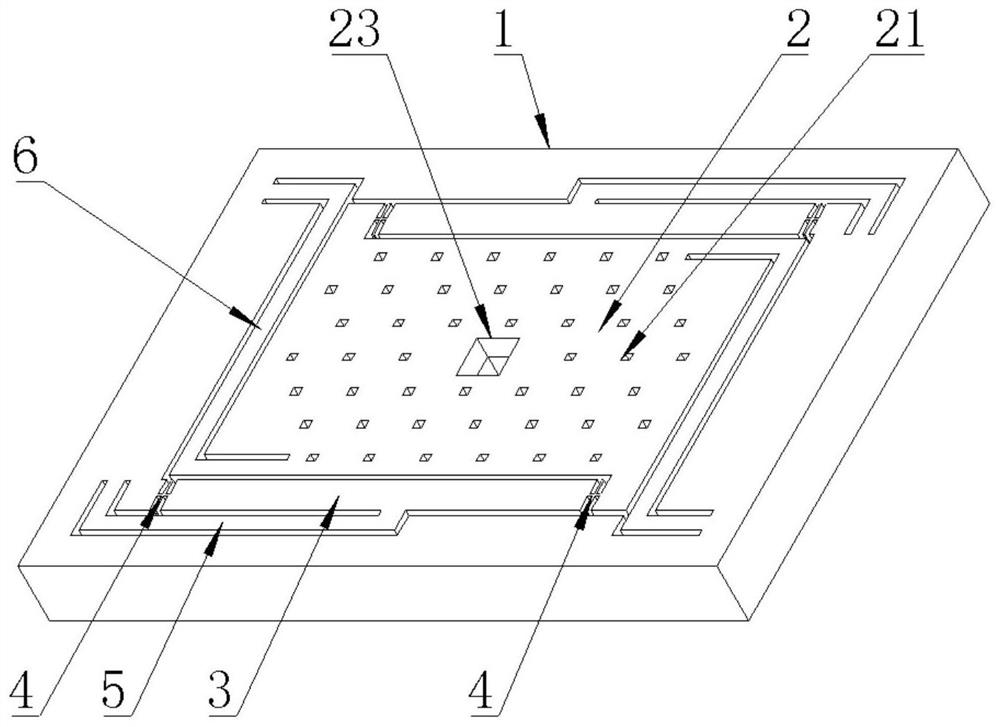
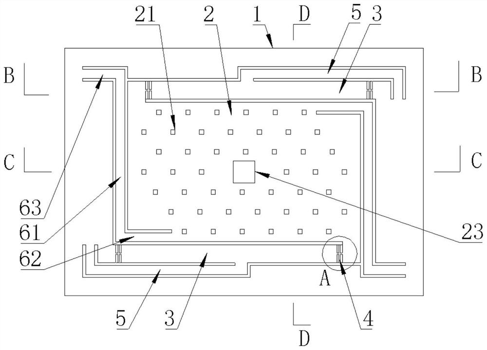
[0061] see Figure 5 , as a specific embodiment of the piezoresistive acceleration sensor provided by the present invention, the second support beam 6 includes:

[0062] The main body section 61 is located in the active cavity and parallel to the side of the mass block 2 close to the main body section 61;

[0063] The first bending section 62 is set at an angle with the main section 61, one end is connected to one end of the main section 61, and the other end is connected to the mass block 2; and

[0064] The second bent section 63 is set at an angle with the main section 61 , one end is connected to the other end of the main section 61 , and the other end is connected to the mass block 2 .

[0065] Specifically, the second support beam 6 has a bent structure, and the main body section 61 and the first bent section 62 and the second bent section 63 at both ends of its long axis are Z-shaped. The main body section 61 is parallel to the longitudinal sides of the proof mass 2, ...


PUM


Abstract

The invention provides a piezoresistive acceleration sensor, belonging to the field of acceleration sensors, comprising: a frame with a movable chamber inside; a mass block movable in the movable chamber; a sensitive beam with pressure-sensitive The measuring section of the element is connected to the frame and the mass block; and the first support beam, the two ends of the long axis are respectively connected to the sensitive beam and the frame, and the stiffness of the first support beam in the sensing direction of the mass block is smaller than that in the sensing direction of the mass block Stiffness in the vertical direction. Reinforce the sensitive beam by the first support beam, the first support beam has a smaller degree in the sense direction of the mass block, so that the piezoresistive acceleration sensor maintains a higher sensitivity; the first support beam is perpendicular to the sense direction of the mass block The rigidity in the direction is large, so that when the sensor faces the acceleration in a direction other than the sensitive direction, the deformation of the sensitive beam and the measuring section is reduced, and the breaking of the sensitive beam and the measuring section is avoided.

Description

technical field [0001] The invention belongs to the technical field of acceleration sensors, and more specifically relates to a piezoresistive acceleration sensor. Background technique [0002] Micro-Electro-Mechanical Systems (MEMS, Micro-Electro-Mechanical System), also known as micro-electro-mechanical systems, micro-systems, micro-machines, etc., refers to high-tech devices with a size of a few millimeters or even smaller. MEMS acceleration sensor is a sensor made by micromachining technology. According to different working principles, MEMS acceleration sensors can be divided into capacitive, piezoresistive, heat flow, piezoelectric and resonance. Compared with other forms of MEMS acceleration sensors, MEMS piezoresistive acceleration sensors have been widely used because of their simple processing technology, convenient testing and low cost. [0003] The general MEMS piezoresistive acceleration sensor is based on the piezoresistive effect of semiconductors and consist...

Claims


Application Information

Patent Timeline
Patent Type & Authority Patents(China)
IPC IPC(8): G01P15/12
CPCG01P15/12
Inventor 张广平王伟忠
Owner THE 13TH RES INST OF CHINA ELECTRONICS TECH GRP CORP
Why Eureka
Try Eureka