Insulation rod

A technology of insulating rods and working rods, which is applied in the direction of overhead lines/cable equipment, switchgear, electrical components, etc., can solve the problems of insufficient length of insulating rods, and achieve the effects of improving operating efficiency, simple structure, and convenient operation

Inactive Publication Date: 2019-04-09
STATE GRID CORP OF CHINA +1
View PDF9 Cites 0 Cited by
  • Summary
  • Abstract
  • Description
  • Claims
  • Application Information

AI Technical Summary

Problems solved by technology

[0004] In order to solve the problem of insufficient length of insulating rods, the present invention provides an insulating rod

Method used


Image

  • Insulation rod
  • Insulation rod
  • Insulation rod

Examples


Embodiment Construction

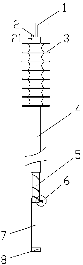
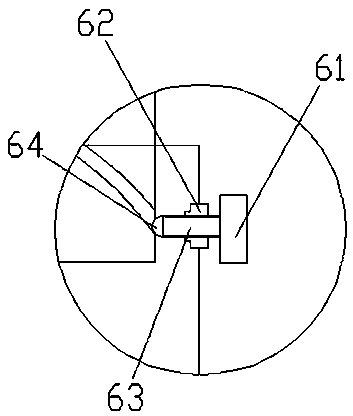
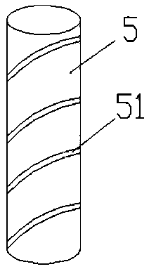
[0019] as attached Figures 1 to 4 As shown, a kind of insulating rod, comprises working rod 4 and hand-held rod 7,: described working rod 4 top is provided with working head 1, is provided with insulator 3 at the upper end of working rod 4, and described working rod 4 bottoms and rotating rod 5 is fixedly connected, the outer surface of the rotating rod 5 is provided with a surrounding groove 51, the interior of the handle rod 7 is hollow, the rotating rod 5 is installed inside the handle rod 7, and a long moving chute 71 is provided on the outer surface of the handle rod 7, A moving device 6 is arranged in the chute 71, and the moving device 6 can drive the rotating rod 5 to move up and down along the track of the groove 51.

[0020] Working process of the present invention is as follows:

[0021] Adjust the length of the insulating rod, the outer surface of the rotating rod 5 is provided with a surrounding groove 51, the rotating rod 5 is fixedly connected with the working...


PUM

PropertyMeasurementUnit
Lengthaaaaaaaaaa

Abstract

The invention provides an insulation rod. The insulation rod comprises a working rod and a handhold rod, wherein a working head is arranged above the working rod, an insulator is arranged at an upperend of the working rod, the bottom of the working rod is fixedly connected with a rotation rod, a circumferential encircling groove is formed in an outer surface of the rotation rod, the handhold rodis hollow, the rotation rod is arranged in the handhold rod, an elongate moving sliding groove is formed in an outer surface of the handhold rod, and a moving device is arranged in the sliding grooveand can drive the rotation rod to move upwards ad downwards along a groove track. By the moving device, the rotation rod is driven, the working rod is raised, and the purpose of increasing the total length is achieved; and the insulator is arranged on the working rod, so that power bridging distance of the insulator rod is farther, and the safety of an operator is ensured. The insulator rod is simple in structure and is convenient to operate, the safety operation is ensured, and the operation efficiency is improved.

Description

technical field [0001] The invention relates to the technical field of electrical equipment, in particular to an insulating rod. Background technique [0002] In the past, the power inspection of 10kV overhead lines and the connection of grounding wires were carried out on the poles. Large ropes for electrical appliances and grounding wires, upper pole, determine the station position, (after the ground personnel tie the electroscope to the large rope), the boarding personnel connect the electroscope through the large rope for electric inspection, and use the large rope to check the voltage after checking that there is no voltage. The electroscope is passed to the personnel under the pole, (after the ground personnel tie the grounding rod to the big rope) the climber gets the grounding rod through the big rope, and finally completes the task of hanging the grounding wire. [0003] At present, the drop-type self-falling in the 10kv pole-mounted distribution station area meets...

Claims


Application Information

Patent Timeline
IPC IPC(8): H02G1/02H02B3/00
CPCH02B3/00H02G1/02
Inventor 靳志国李瑞云张滨张国兵李嵩刘国栋王伟峰韩光林伟李博凡郭明奇周捷王莹莹
Owner STATE GRID CORP OF CHINA
Why Eureka
Try Eureka