Rotor of motor and motor

A rotor and rotor shaft technology, which is applied in the direction of electric components, electrical components, electromechanical devices, etc., can solve problems such as lack of heat dissipation, achieve good heat dissipation effect, increase the overall length, and improve the connection stability.

Active Publication Date: 2020-04-03
ZHONGQUAN PUMP IND GROUP ZHEJIANG
View PDF6 Cites 0 Cited by
  • Summary
  • Abstract
  • Description
  • Claims
  • Application Information

AI Technical Summary

Problems solved by technology

[0003] The outer rotor of the current motor does not have the function of heat dissipation, so it is necessary to improve the outer rotor motor

Method used


Image

  • Rotor of motor and motor
  • Rotor of motor and motor
  • Rotor of motor and motor

Examples


Embodiment 1

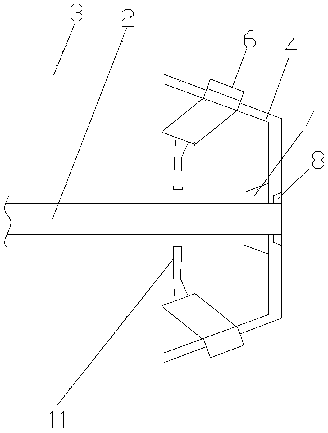
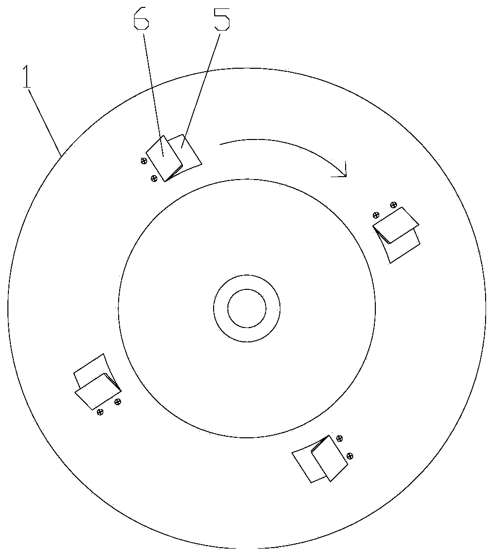
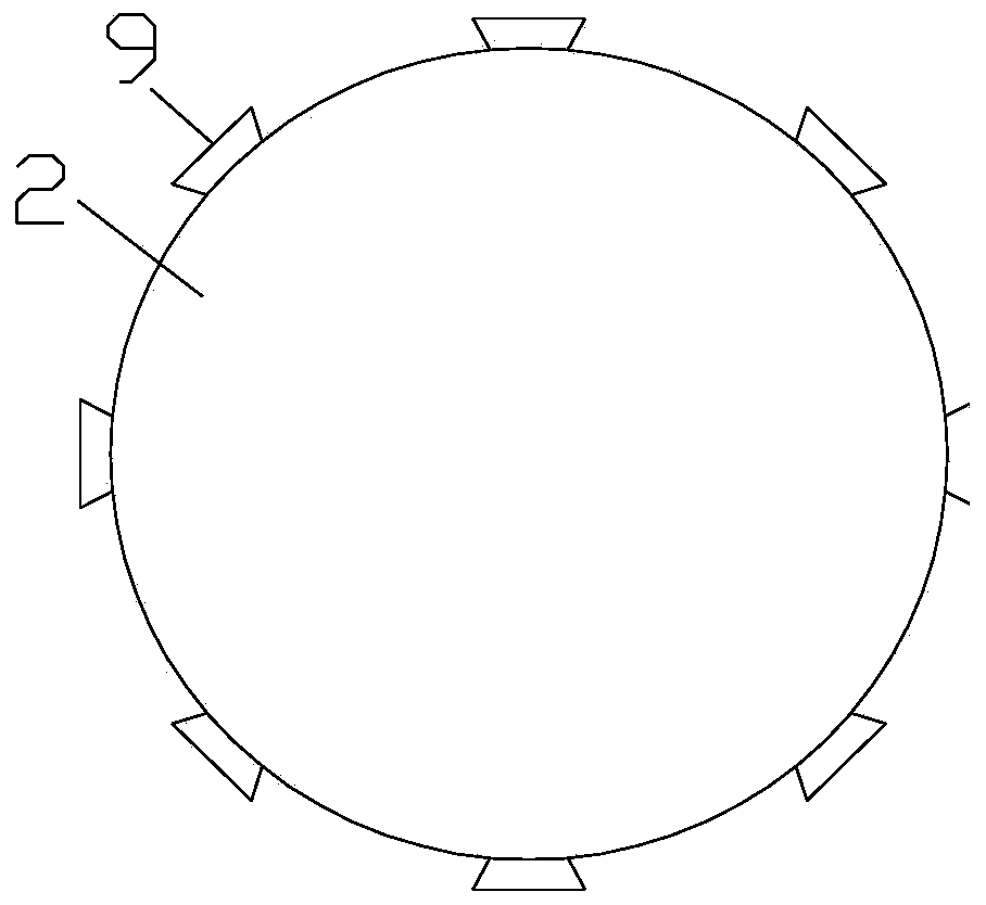
[0026] Such as Figure 1-4 As shown, a rotor of a motor includes an outer rotor housing 1 and a rotor shaft 2, the outer rotor housing 1 includes a cylindrical section 3 and a cone-shaped section 4, and the cylindrical section 3 and the cone-shaped section The section 4 is integrally arranged, and the middle part of the bottom of the cone-shaped section 4 is provided with a connecting hole (not shown) that matches the rotor shaft 2, and the end of the rotor shaft 2 is inserted into the connecting hole, and the rotor shaft 2 is suspended in the outer rotor casing 1 through the connection hole, and the air inlet 5 is arranged on the inclined surface of the cone-shaped section 4, and the air inlet 5 is inserted with a deflector 6, and the deflector 6 is in the form of The head end of the deflector 6 is located outside the cone-shaped section 4 and forms an air scraping inlet with the air inlet. The air scraping inlet is arranged at an acute angle. The opening direction of the air...

Embodiment 2

[0029] Such as Figure 1-4 As shown, a rotor of a motor includes an outer rotor housing 1 and a rotor shaft 2, the outer rotor housing 1 includes a cylindrical section 3 and a cone-shaped section 4, and the cylindrical section 3 and the cone-shaped section The section 4 is integrally arranged, and the middle part of the bottom of the cone-shaped section 4 is provided with a connecting hole (not shown) that matches the rotor shaft 2, and the end of the rotor shaft 2 is inserted into the connecting hole, and the rotor shaft 2 is suspended in the outer rotor casing 1 through the connection hole, and the air inlet 5 is arranged on the inclined surface of the cone-shaped section 4, and the air inlet 5 is inserted with a deflector 6, and the deflector 6 is in the form of The head end of the deflector 6 is located outside the cone-shaped section 4 and forms an air scraping inlet with the air inlet. The air scraping inlet is arranged at an acute angle. The opening direction of the air...


PUM


Abstract

The invention discloses a rotor of a motor and the motor. The rotor comprises an outer rotor shell and a rotor shaft, the outer rotor shell comprises a circular tube-shaped section and a conical cylinder-shaped section; the circular tube-shaped section and the conical cylinder-shaped section are integrally arranged; a connecting hole matched with the rotor shaft is formed in the middle of the cylinder bottom of the conical cylinder-shaped section; the tail end of the rotor shaft is inserted into the connecting hole; the rotor shaft is suspended in the outer rotor shell through the connecting hole; an air inlet is formed in the inclined surface of the conical cylinder-shaped section; a flow deflector is inserted into the air inlet; the flow deflector is arranged in an obtuse angle shape; the head end of the flow deflector is located outside the conical cyinder-shaped section, an air scraping inlet is formed by the head end of the flow deflector and the air inlet, the air scraping inletis arranged in an acute angle shape, the opening direction of the air scraping inlet is the same as the rotating direction of the outer rotor shell, the tail end of the flow deflector is located in the conical cylinder-shaped section, and the flow deflector is fixedly connected with the conical cylinder-shaped section. The rotor of the motor has a good heat dissipation effect.

Description

technical field [0001] The invention relates to a motor rotor and the motor. Background technique [0002] A motor is an electromagnetic device that converts or transmits electrical energy according to the law of electromagnetic induction, or converts one form of electrical energy into another form of electrical energy. A motor converts electrical energy into mechanical energy, and a generator converts mechanical energy into electrical energy. Its main function is to generate driving torque as a power source for electrical appliances or various machinery. [0003] The outer rotor of the current motor does not have the function of heat dissipation, so it is necessary to improve the outer rotor motor. Contents of the invention [0004] The technical problem to be solved by the present invention is to provide a motor rotor and motor with good heat dissipation effect. [0005] In order to solve the above problems, the present invention adopts the following technical solutio...

Claims


Application Information

Patent Timeline
IPC IPC(8): H02K1/32H02K5/20H02K5/10
CPCH02K1/32H02K5/10H02K5/20
Inventor 不公告发明人
Owner ZHONGQUAN PUMP IND GROUP ZHEJIANG
Why Eureka
Try Eureka