Predictive direct duty cycle control method for permanent magnet synchronous motor based on variable control-set

A technology of permanent magnet synchronous motor and control method, which is applied to control generators, control electromechanical brakes, control electromechanical transmission devices, etc., can solve the problems of increasing the complexity of the method, increasing the complexity of the control method, and reducing the adaptability of the parameters of the control method.

Active Publication Date: 2019-04-09
TIANJIN POLYTECHNIC UNIV
View PDF6 Cites 5 Cited by
  • Summary
  • Abstract
  • Description
  • Claims
  • Application Information

AI Technical Summary

Problems solved by technology

At present, this type of method outputs a three-stage virtual vector (V 0 -V 1 -V 0 ) research work has achieved good results, and output five-stage (V 0 -V 1 -V 2 -V 1 -V 0 ), and even seven-segment (V 0 -V 1 -V 2 -V 7 -V 2 -V 1 -V 0 ) The extended control set PTC of the virtual vector still needs to assist the SVPWM modulation technology, which increases the complexity of the method
[0007] In the traditional improvement method, the continuous control set PTC needs to use the precise motor parameters, which reduces the parameter adaptability of the control method; the multi-vector PTC and the extended control set PTC need the assistance of the modulator to output the voltage space vector to control the motor, which increases the The complexity of the control method

Method used


Image

  • Predictive direct duty cycle control method for permanent magnet synchronous motor based on variable control-set
  • Predictive direct duty cycle control method for permanent magnet synchronous motor based on variable control-set
  • Predictive direct duty cycle control method for permanent magnet synchronous motor based on variable control-set

Examples


specific Embodiment

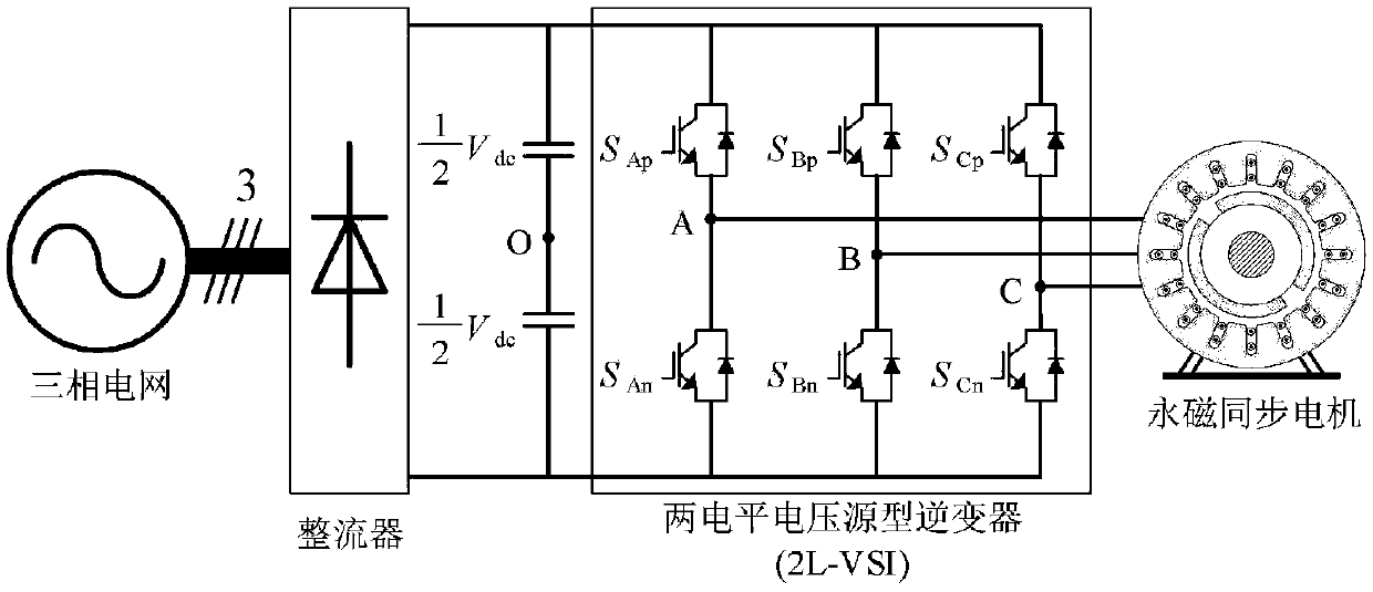
[0131] In this embodiment, the TMS320F28377D microprocessor of TI Company is selected to perform formula calculation, duty ratio optimization, and generate switching tube switching signals. The circuit structure is attached figure 1 As shown, the left side of the figure is a three-phase power grid and an uncontrolled rectifier bridge, where S Ap , S Bp , S Cp , S An , S Bn and S Cn Respectively represent the switching states of the upper and lower arm IGBTs of the 2L-VSI three-phase (A, B, and C), with "1" indicating that the IGBT is in the on state, and "0" indicating that the IGBT is in the off state; V dc is the DC side capacitor voltage; the right side is a two-level voltage source inverter, controlling a permanent magnet synchronous motor.

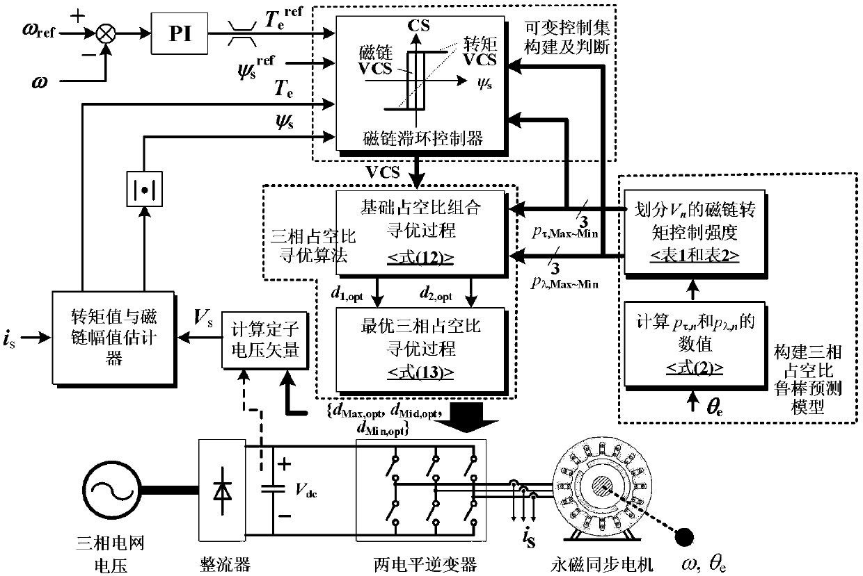
[0132] A direct predictive duty cycle control method based on variable control set of the present invention is mainly composed of three parts: three-phase duty cycle robust prediction model, variable control set and three-phase ...


PUM


Abstract

The invention discloses a predictive direct duty cycle control method for a permanent magnet synchronous motor based on a variable control-set. The method comprises the steps of computing a voltage vector of a stator at a previous control moment, wherein the computation adopts a new vector synthesis mechanism; collecting three-phase current values of the motor stator, and estimating a flux linkageamplitude and an electromagnetic torque value of the motor stator at a current control moment; collecting a rotation speed of the motor and an electrical degree of a rotor at the current control moment; computing effect intensities of three-phase basic voltage vectors on the flux linkage amplitude and the electromagnetic torque value; building a three-phase duty cycle robust prediction model; dividing the three-phase basic voltage vectors into a strong level, a middle level and a weak level for electromagnetic torque value and flux linkage amplitude controller intensities; separately buildinga torque variable control-set and a flux linkage variable control-set; selecting 11 basic duty cycle combinations; determining the optimal basic duty cycle combination; and determining optimal three-phase duty cycles. According to the method provided by the invention, the excellent torque dynamic control performance of the prior art is kept, and the five-part type or seven-part type voltage vector control motor is not needed to be output without the assistance of a modulator.

Description

technical field [0001] The invention belongs to the technical field of permanent magnet synchronous motor control, and more specifically relates to a method for directly predicting duty ratio control of permanent magnet synchronous motors based on variable control sets. Background technique [0002] Permanent magnet synchronous motor (Permanent magnet synchronous motor, PMSM) has the advantages of simple structure, high power factor, wide speed range, etc., and has been widely used in the fields of numerical control machine tools, elevator control and traction drive. In recent years, Finite Control-Set Predictive Torque Control (FCS-PTC), as a kind of closed-loop control method using online optimization, can significantly improve the torque dynamic performance of the motor, and has achieved great success in the field of PMSM drive. successfully applied. [0003] When FCS-PTC is used to control the PMSM drive system (Two-level Voltage Source Inverter fed PMSMs Drive System, ...

Claims


Application Information

Patent Timeline
IPC IPC(8): H02P21/00H02P21/14H02P21/18H02P21/20H02P21/22
CPCH02P21/0017H02P21/14H02P21/18H02P21/20H02P21/22
Inventor 周湛清乔升威耿强王慧敏
Owner TIANJIN POLYTECHNIC UNIV
Why Eureka
Try Eureka