Tube stock cutting device for automotive part manufacturing

A technology for auto parts and cutting devices, applied in manufacturing tools, other manufacturing equipment/tools, metal processing, etc., can solve problems such as low work efficiency, pipe deformation, pipe incision deformation, etc., achieve small box, reduce occupation, The effect of improving work efficiency

Active Publication Date: 2019-04-12
宁波隆锐机械制造有限公司
View PDF9 Cites 2 Cited by
  • Summary
  • Abstract
  • Description
  • Claims
  • Application Information

AI Technical Summary

Problems solved by technology

[0003] At present, when many pipe cutting machines cut steel pipes, there will be a problem of deformation of the pipe incision, especially for thin-walled pipes. Many companies have a headache for this; The cutting force and the extrusion force of the downward movement of the cutting knife, when the cutting speed of the cutting knife is not fast enough, and when the cutting knife applies a large extrusion force to the pipe, the excessive extrusion force will cause the pipe to The incision is deformed, and the pipe end needs to be corrected before it can be used in the next process
Moreover, many pipe cutting machines currently on the market cannot completely guarantee that the pipe incision will not be deformed; and the existing pipe cutting machines need manual operation to realize feeding and discharging before and after each cutting. The work efficiency of the material production method is very low

Method used


Image

  • Tube stock cutting device for automotive part manufacturing
  • Tube stock cutting device for automotive part manufacturing
  • Tube stock cutting device for automotive part manufacturing

Examples


Embodiment 1

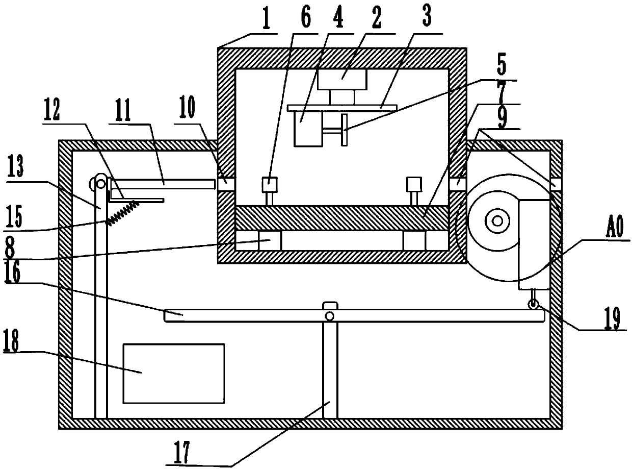
[0027] Basic as attached figure 1 Shown: a pipe cutting device for auto parts manufacturing, including a box 1, the box 1 is provided with a feed port 9, the box 1 includes a cutting chamber and a power transmission chamber arranged up and down, the cutting The side wall of the chamber is provided with a feed port 9 and a discharge port 10. The telescopic rod provided on the top of the cutting chamber is an electric telescopic rod 2, and the bottom of the electric telescopic rod 2 is fixedly provided with a fixed plate 3. The bottom of the plate 3 is fixedly provided with a motor 4, the rotating shaft of the motor 4 is connected with a cutting knife 5, and a cutting table is arranged below the cutting knife 5, and the cutting table includes a support plate 7 and four support blocks 8, and the four blocks The support blocks 8 are evenly and fixedly arranged on both sides of the bottom of the cutting chamber, the support plate 7 is arranged above the support block 8, and two set...

Embodiment 2

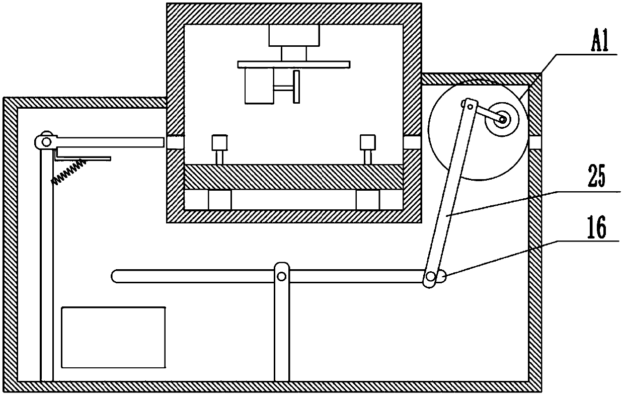
[0037] Basic as attached image 3 Shown:

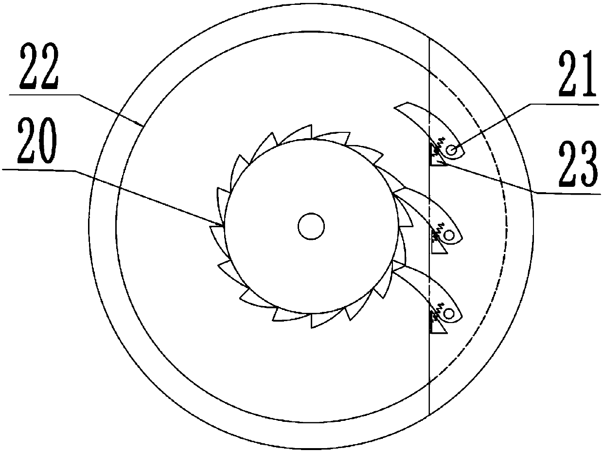
[0038] The difference between embodiment two and embodiment one is that the feed structure is different, such as Figure 4 As shown, the feed structure includes a connecting rod 24, a second swing rod 25, a ratchet 20, a transmission disc 22 and a pawl 21, and the ratchet 20 and the transmission disc 22 are fixedly connected to the rotating shaft and rotate with the outer wall of the power transmission chamber Connected, the transmission disc 22 is used to move the pipe to the cutting chamber, the circumferential surface of the transmission disc 22 is against the upper part of the pipe to be cut, and the two ends of the connecting rod 24 are respectively connected to the first swing rod 16 and the second One end of the two swing rods 25 is rotatably connected, and the other end of the second fork rod 25 is rotatably connected to the rotating shaft of the transmission disc 22, and the first fork rod 16, the connecting rod 24 and the s...


PUM


Abstract

The invention relates to the field of automotive part manufacturing machining, in particular to a tube stock cutting device for automotive part manufacturing. The tube stock cutting device for automotive part manufacturing comprises a box body, a feeding opening and a discharging opening are formed in the box body, the box body comprises a cutting chamber and a power transmission chamber which arearranged up and down, and an electric telescopic rod is arranged at the top of the interior of the cutting chamber. A fixed plate is arranged at the bottom of the electric telescopic rod, a motor isarranged at the bottom of the fixed plate, a cutting knife is connected to a rotary shaft of the motor, and a cutting table is arranged below the cutting knife. The cutting table comprises a supporting plate and supporting blocks, the supporting blocks are arranged on two sides of the bottom of the interior of the cutting chamber, the supporting plate is arranged above the supporting blocks, clamping structures are arranged on two sides of the supporting blocks, and the clamping structures, the feeding opening and the discharging opening are located on a same straight line. The power transmission chamber is provided with a discharging structure, a transmission structure and a feeding structure. According to the tube stock cutting device for automotive part manufacturing, after clamping andcutting of tube stocks are realized, functions of discharging, correcting and automatic circulation of the tube stocks can be realized, and the automatic degree is high.

Description

technical field [0001] The invention relates to the field of auto parts manufacturing and processing, in particular to a pipe material cutting device for auto parts manufacturing. Background technique [0002] With the improvement of people's living standards, people consume more and more cars, and the auto parts market has become larger and larger. In recent years, auto parts manufacturers have also developed rapidly. Steel pipes are an important part of automobile structural components, and their total demand continues to rise with the increase in automobile production, so the market for pipe cutting machines is also growing. [0003] At present, when many pipe cutting machines cut steel pipes, there will be a problem of deformation of the pipe incision, especially for thin-walled pipes. Many companies have a headache for this; The cutting force and the extrusion force of the downward movement of the cutting knife, when the cutting speed of the cutting knife is not fast e...

Claims


Application Information

Patent Timeline
Patent Type & Authority Applications(China)
IPC IPC(8): B23P23/04B23Q7/00
CPCB23P23/04B23Q7/00
Inventor 项文增
Owner 宁波隆锐机械制造有限公司
Why Eureka
Try Eureka