Automatic feeding and discharging stirrer for building

An automatic material feeding and construction technology, which is applied in the direction of cement mixing device, unloading device, and selling raw material supply device, etc., can solve the problems of reducing construction efficiency and cumbersome feeding, and achieve the effect of high efficiency and sufficient mixing

Inactive Publication Date: 2019-04-12
李清华
View PDF6 Cites 5 Cited by
  • Summary
  • Abstract
  • Description
  • Claims
  • Application Information

AI Technical Summary

Problems solved by technology

[0003] When the current mixer is mixing concrete, either add water to the mixing tank and then add sand and cement, or add sand and cement first, and then add water for mixing, but no matter what form it is, it cannot be mixed in a short period of time. In order to achieve a good mixing effect, and the existing device is also relatively cumbersome in terms of feeding, thus reducing the construction efficiency

Method used


Image

  • Automatic feeding and discharging stirrer for building
  • Automatic feeding and discharging stirrer for building
  • Automatic feeding and discharging stirrer for building

Examples


Embodiment 2

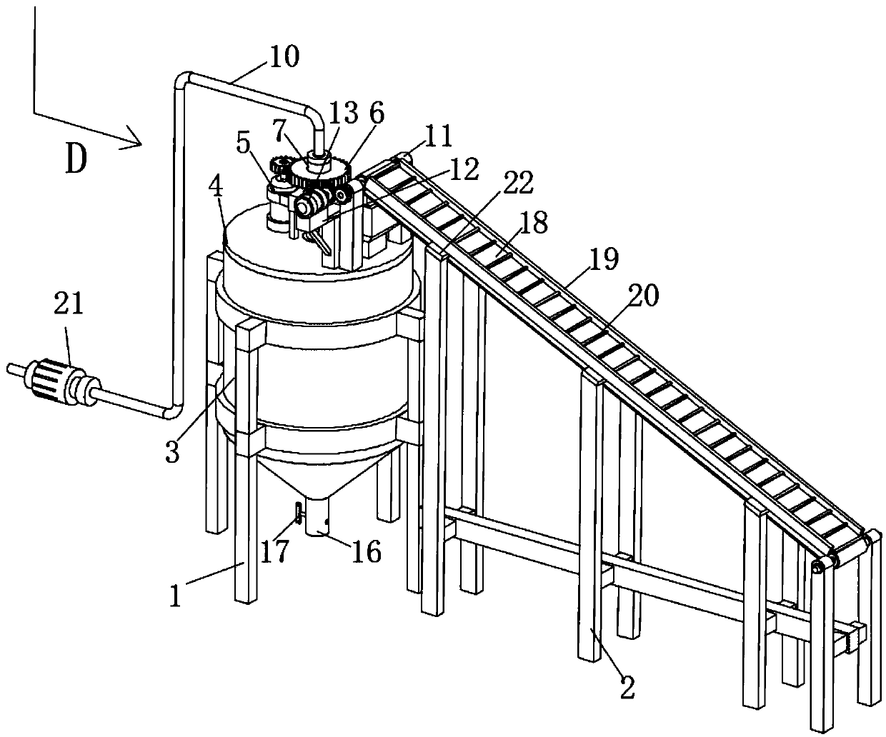
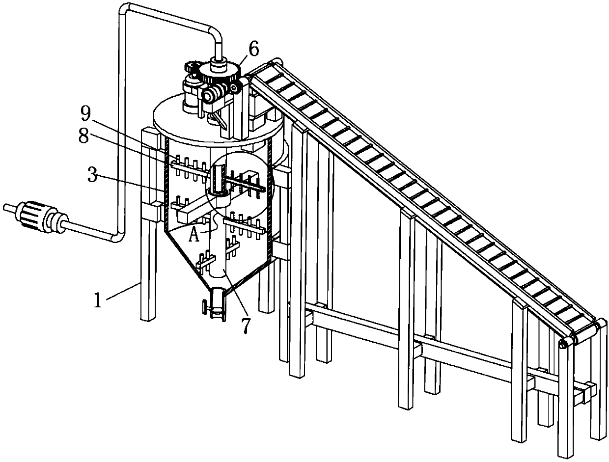
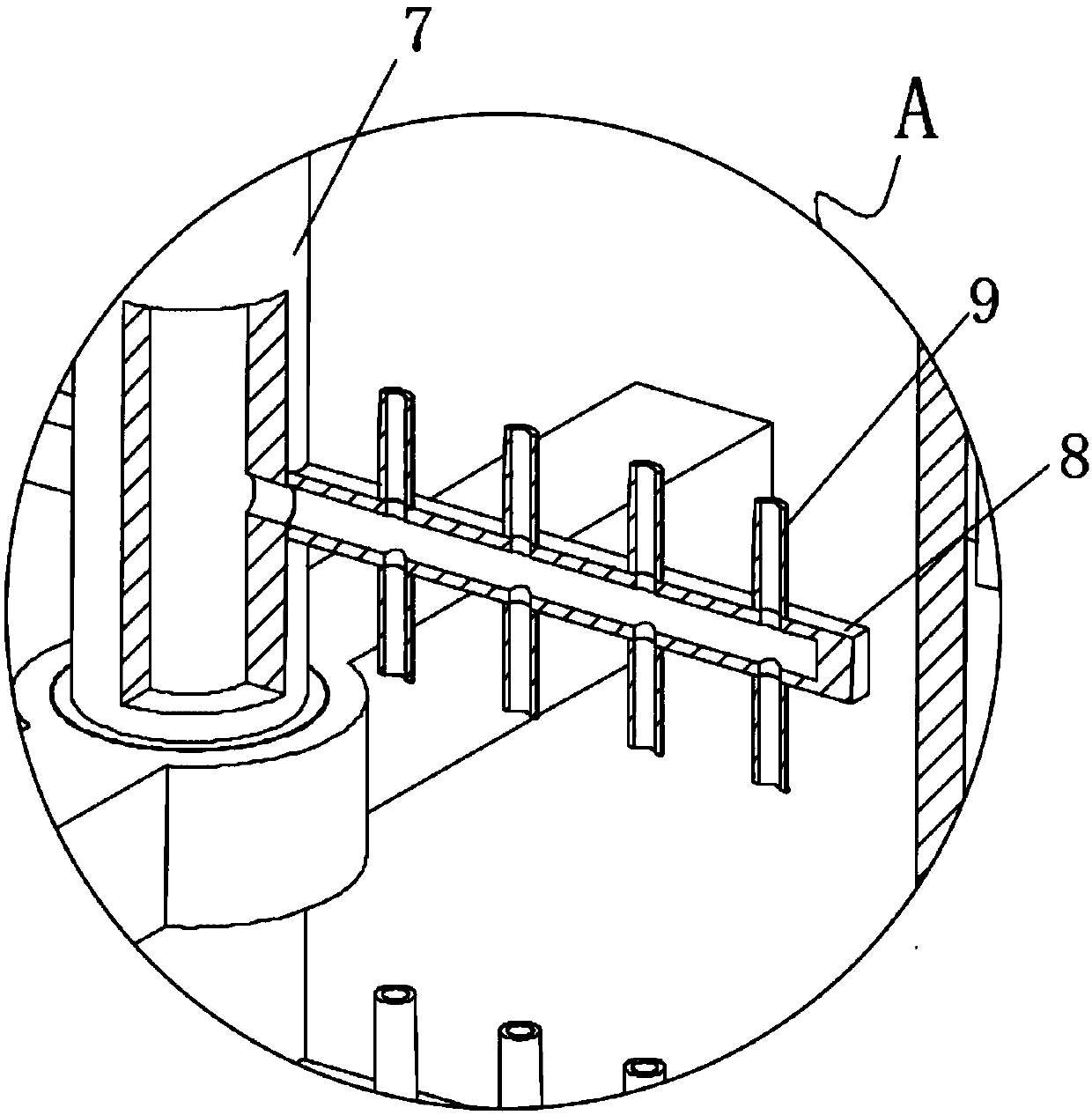
[0029] Embodiment 2: A mixer for automatic feeding and discharging for construction, including a stirring tank support 1 and a transmission mechanism support 2, a stirring tank 3 is fixedly supported above the stirring tank support 1, and the top of the mixing tank 3 is sealed with a tank cover 4. The upper surface of the tank cover 4 is fixedly welded with a stirring motor 5, and the upper end of the output shaft of the stirring motor 5 is fixedly welded with a stirring drive gear, and the inner side of the stirring drive gear is meshed with a stirring shaft gear 6, and the middle part of the stirring shaft gear 6 is fixedly interspersed There is a hollow stirring shaft 7, and the lower end of the hollow stirring shaft 7 penetrates into the inside of the stirring tank 3, the surface of the hollow stirring shaft 7 is fixedly provided with a plurality of stirring rods 8, and the upper and lower surfaces of the stirring rods 8 are fixedly connected with a plurality of stirring sup...

Embodiment 3

[0031]Embodiment 3: A mixer for automatic feeding and discharging for construction, including a stirring tank support 1 and a transmission mechanism support 2, a stirring tank 3 is fixedly supported above the stirring tank support 1, and the upper sealing cover of the mixing tank 3 is closed with a tank cover 4. The upper surface of the tank cover 4 is fixedly welded with a stirring motor 5, and the upper end of the output shaft of the stirring motor 5 is fixedly welded with a stirring drive gear, and the inner side of the stirring drive gear is meshed with a stirring shaft gear 6, and the middle part of the stirring shaft gear 6 is fixedly interspersed There is a hollow stirring shaft 7, and the lower end of the hollow stirring shaft 7 penetrates into the inside of the stirring tank 3, the surface of the hollow stirring shaft 7 is fixedly provided with a plurality of stirring rods 8, and the upper and lower surfaces of the stirring rods 8 are fixedly connected with a plurality ...

Embodiment 4

[0035] The difference from Embodiment 1 is that: the stirring tank support 1 is provided with a plurality of supporting legs, and there are two groups of four supporting legs.

[0036] Further, in the above solution, the two sets of supporting legs are center-symmetrical with respect to the vertical central axis of the stirring tank 3 , and the supporting legs can play a good stabilizing effect on the stirring tank 3 .


PUM


Abstract

The invention discloses an automatic feeding and discharging stirrer for building. The automatic feeding and discharging stirrer for building comprises a stirring tank bracket and a conveying mechanism bracket; a stirring tank is fixedly supported on the stirring tank bracket, and a tank cover is arranged on the stirring tank in a sealing and covering mode; a stirring motor is fixedly welded to the upper surface of the tank cover, and a stirring driving gear is fixedly welded to the upper end of an output shaft of the stirring motor; the inner side of the stirring driving gear meshes with a stirring shaft gear, a hollow stirring shaft is fixedly inserted into the middle of the stirring shaft gear in a penetrating mode, and the lower end of the hollow stirring shaft penetrates into the stirring tank; and a plurality of stirring rods are fixedly arranged on the surface of the hollow stirring shaft, and a plurality of stirring branch rods are fixedly connected to the upper surface and thelower surface of the stirring rods. According to the automatic feeding and discharging stirrer for building, the output shaft of the stirring motor rotates to enable the hollow stirring shaft to rotate at high speed, water flows out from water outlets of the stirring branch rods while materials are stirred by the stirring rods at high speed, and therefore concrete is stirred quite efficiently andfully.

Description

technical field [0001] The invention relates to the technical field of construction devices, in particular to a mixer for automatic feeding and discharging for construction. Background technique [0002] Concrete, referred to as "concrete" for short, refers to the collective name of engineering composite materials in which aggregates are cemented into a whole by cementitious materials. Generally speaking, the term concrete refers to the cement concrete obtained by using cement as the cementitious material, sand and stone as the aggregate; mixed with water (may contain admixtures and admixtures) in a certain proportion, and stirred. Concrete, which is widely used in civil engineering, is a general term for buildings and structures. It is an artificial environment created by people using material and technical means and certain scientific laws, Feng Shui concepts and aesthetic principles to meet the needs of social life. Architecture is a space for people to live and use that...

Claims


Application Information

Patent Timeline
Patent Type & Authority Applications(China)
IPC IPC(8): B28C5/16B28C7/06B28C7/12B28C7/16
CPCB28C5/16B28C7/06B28C7/12B28C7/16
Inventor 李清华
Owner 李清华
Why Eureka
Try Eureka