Gas discharging device, fuel tank and automobile

A technology for exhaust devices and fuel tanks, which is applied in power plants, packaging, and vehicle parts, and can solve problems such as disengagement and gas leakage at joints, and achieve the effects of balancing pressure, reducing exhaust emissions, and making full use of fuel

Inactive Publication Date: 2019-04-12
河北世昌汽车部件股份有限公司
View PDF0 Cites 1 Cited by
  • Summary
  • Abstract
  • Description
  • Claims
  • Application Information

AI Technical Summary

Problems solved by technology

[0006] In view of this, the embodiments of the present invention provide an exhaust device, a fuel tank, and a vehicle, aiming to solve the problem of easy gas leakage or even disengagement at the joint between the pipeline and the liquid collector in the prior art

Method used


Image

  • Gas discharging device, fuel tank and automobile
  • Gas discharging device, fuel tank and automobile
  • Gas discharging device, fuel tank and automobile

Examples


Embodiment Construction

[0040] In the following description, specific details such as specific system structures and technologies are presented for the purpose of illustration rather than limitation, so as to thoroughly understand the embodiments of the present invention. It will be apparent, however, to one skilled in the art that the invention may be practiced in other embodiments without these specific details. In other instances, detailed descriptions of well-known systems, devices, circuits, and methods are omitted so as not to obscure the description of the present invention with unnecessary detail.

[0041] The technical solutions of the present invention will be clearly and completely described below in conjunction with the accompanying drawings.

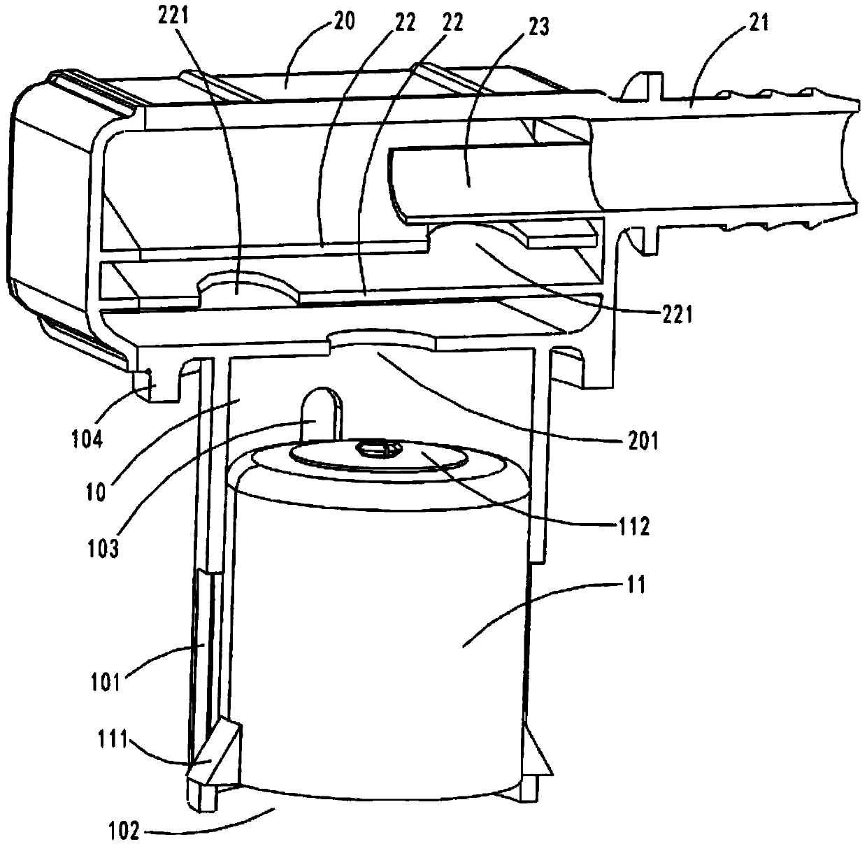
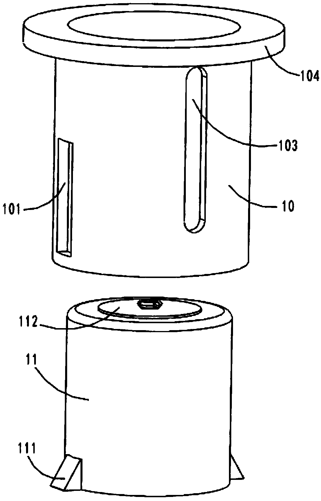
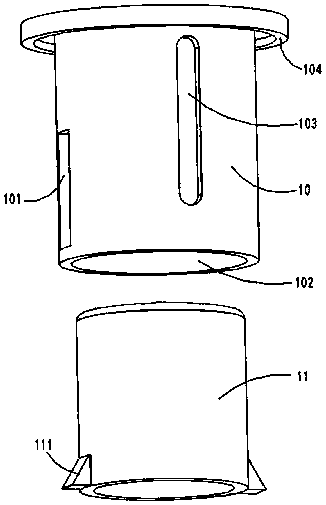
[0042] An embodiment of the present invention provides an exhaust device, combined with figure 1 , Figure 6 and Figure 7 As shown, the exhaust device includes a valve body 10 and a housing 20 . The valve body 10 is used to be arranged in the ...


PUM


Abstract

The invention relates to the technical field of automobiles, in particular to a gas discharging device. The gas discharging device comprises a valve body and a casing; the valve body is used for beingarranged in a cavity of the fuel tank; a wall plate of the valve body is connected with a wall plate of the fuel tank; a cavity of the valve body is communicated with the cavity of the fuel tank; thecasing is positioned above the valve body in a vertical direction; a bottom plate of the casing is connected with the wall plate of the valve body; a through hole is formed in the bottom plate of thecasing; a cavity of the casing is communicated with the cavity of the valve body through the through hole; and a joint for being connected with a pipeline is arranged on the upper part of the casing.The gas discharging device integrates the casing for storing leaked fuel and the fuel tank into a whole structure, the fuel tank and a carbon tank are communicated through one pipeline, and two joints are arranged between the pipeline and a liquid collector, so that a connecting structure between the fuel tank and the carbon tank is more stable, and the risk that gas leakage exists, even the pipeline is separated in the joint position caused by vibration is reduced.

Description

technical field [0001] The invention relates to the technical field of automobiles, in particular to an exhaust device, a fuel tank and an automobile. Background technique [0002] The fuel tank is an important component of the car and is used to store fuel. Because the fuel is volatile, the fuel tank will be filled with evaporated gas, so the pressure in the fuel tank will increase accordingly. In order to balance the pressure in the fuel tank and avoid danger, an exhaust pipe is arranged on the fuel tank, and the fuel vapor is discharged into the outside atmosphere through the exhaust pipe. However, fuel vapor will reduce air quality and pollute the environment, and direct discharge of fuel vapor will also cause waste of resources. [0003] In order to solve the above problems, a carbon canister is arranged between the fuel tank and the engine in the prior art, and activated carbon with strong adsorption capacity is filled in the carbon canister; after the gas in the fue...

Claims


Application Information

Patent Timeline
Patent Type & Authority Applications(China)
IPC IPC(8): B60K15/035
CPCB60K15/035
Inventor 徐飞
Owner 河北世昌汽车部件股份有限公司
Why Eureka
Try Eureka