Sealing structure of joint of insulating blocks of B type enclosure system

A technology of sealing structure and insulating block, which is applied in engine sealing, pipeline protection, pipeline protection through heat insulation, etc., can solve problems such as extrusion and friction of insulating block, bulkhead deformation, and tightness failure at the joint of insulating block. Achieve the effects of preventing extrusion, convenient installation and operation, and preventing damage

Active Publication Date: 2019-04-12
HUDONG ZHONGHUA SHIPBUILDINGGROUP
View PDF9 Cites 5 Cited by
  • Summary
  • Abstract
  • Description
  • Claims
  • Application Information

AI Technical Summary

Problems solved by technology

During the loading and unloading process of the cargo hold, the temperature will change to a certain extent, which will cause the deformation of the bulkhead and cause extrusion and friction between the insulating blocks. The ordinary sealing method of the insulating block connection may not be able to cope with this situation. Lead to tightness failure at the junction of insulating blocks

Method used


Image

  • Sealing structure of joint of insulating blocks of B type enclosure system
  • Sealing structure of joint of insulating blocks of B type enclosure system
  • Sealing structure of joint of insulating blocks of B type enclosure system

Examples


Embodiment 1

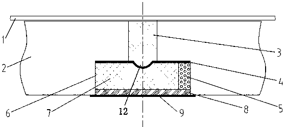
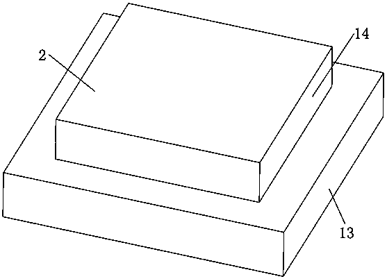
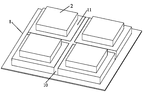
[0033] Embodiment 1, the sealing structure of the connection of the insulating blocks of the B-type containment system of the present invention includes a plurality of first insulating blocks 2 fixed at equal intervals on the bulkhead of the cargo hold, and the longitudinal section of the first insulating blocks 2 is in a convex shape. A first gap 10 for filling the first thermal insulation buffer material 3 is formed between the lower sides of two adjacent first insulating blocks 2, the width of the first gap 10 is 20mm-40mm, and the first gap can be set to Ensure that there is a sufficient buffer gap between the two opposing insulating blocks when the bulkhead deforms so as not to squeeze each other. A second gap 11 for arranging the first aluminum foil 4 , the second insulating block 7 , the second heat-insulating buffer material 5 and the sealing elastic material 8 is formed between the upper sides of two adjacent first insulating blocks.

[0034] The center of the first a...

Embodiment 2

[0046] Embodiment 2. The difference between this embodiment and Embodiment 1 is that the width of the first aluminum foil 4 is greater than the width of the first gap 10 and smaller than the width of the second gap 11 . At this time, the guide groove 12 in the center of the first aluminum foil 4 is located in the middle of the first gap 10 .

[0047] After the first aluminum foil 4 is fixed, the second insulating block 7 is fixed, and the second insulating block 7 has two fixing methods:

[0048] The first fixing method is to bond the lower surface of the second insulating block 7 on the bosses of the left and right first insulating blocks (that is, the lower surface of the second insulating block 7 is connected to the left and right first insulating blocks). There is an adhesive layer between the bosses of the block), so that there are certain gaps between the two sides and the left and right first insulation blocks, and then the second insulation is filled between the two ga...


PUM


Abstract

The invention discloses a sealing structure of a joint of insulating blocks of a B type enclosure system. The sealing structure comprises a plurality of first insulating blocks fixed on the wall of acargo hold; a first gap filled with a first thermal-insulation buffer material is formed between the lower sides of every two adjacent first insulating blocks; and a second gap for arranging a first aluminum foil, a second insulating block, a second thermal-insulation buffer material, and a sealing elastic material is formed between the upper sides of every two adjacent first insulating blocks; the first aluminum foils are arranged on the first thermal-insulation buffer materials; the second insulating blocks are arranged on the first aluminum foils; the space between the second insulating blocks and the first insulating blocks is filled with second thermal-insulation buffer materials; the sealing elastic materials are arranged on the surfaces of the second insulating blocks; and second aluminum foils are arranged on the surfaces of the sealing elastic materials. Therefore, a problem of the sealing failure of the insulating block joint due to the thermal expansion and cold contractionat the independent cabin wall is solved effectively; and the extrusion between the insulating blocks is prevented and the sealing performance of the joint is not damaged.

Description

technical field [0001] This patent is a divisional application of the invention patent application 201810831689.0 on July 26, 2018. [0002] The invention relates to the technical field of ship building sealing, in particular to a sealing structure at the joint of insulating blocks of a B-type containment system. Background technique [0003] The Type B containment system ensures the low temperature performance and sealing performance of the cargo compartment by installing an insulating layer. The insulating layer is assembled from custom-made insulating blocks, and the connection method and sealing method between the insulating blocks will affect the performance index of the overall insulating layer. During the process of loading and unloading cargo, the temperature of the cargo compartment will change to a certain extent, which will cause the deformation of the bulkhead, which will cause extrusion and friction between the insulating blocks. Lead to the failure of the tig...

Claims


Application Information

Patent Timeline
Patent Type & Authority Applications(China)
IPC IPC(8): B63B25/12B63B3/56B63B17/00F16L59/02F16J15/10
CPCB63B3/56B63B17/00B63B25/12F16J15/10F16L59/02
Inventor 耿元伟张汇平江克进唐永生陈曙东姜甲志
Owner HUDONG ZHONGHUA SHIPBUILDINGGROUP
Why Eureka
Try Eureka