A uniaxial wing folding mechanism

A wing folding mechanism and folding mechanism technology, applied in the direction of wing adjustment, etc., can solve the problem that it can only be arranged in the middle of the airfoil thickness, the wing folding angle can only reach about 90°, and the influence of the aerodynamic outer wing of the wing, etc. problems, to achieve the effect of easy implementation, easy maintenance, and small footprint

Active Publication Date: 2022-04-08
CHENGDU AIRCRAFT INDUSTRY GROUP
View PDF0 Cites 0 Cited by
  • Summary
  • Abstract
  • Description
  • Claims
  • Application Information

AI Technical Summary

Problems solved by technology

The traditional single-axis wing folding mechanism does not affect the aerodynamic shape. The folding rotation axis can only be arranged in the middle of the airfoil thickness, and the wing folding angle can only reach about 90°. To increase the folding angle, you need Protrude the folded rotation axis from the airfoil surface, and design the envelope bulge, which has a certain influence on the aerodynamic outer wing of the wing

Method used


Image

  • A uniaxial wing folding mechanism
  • A uniaxial wing folding mechanism
  • A uniaxial wing folding mechanism

Examples


Embodiment 1

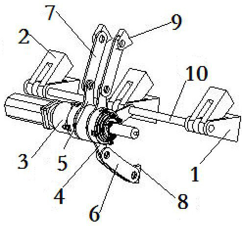
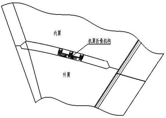
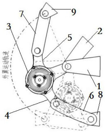
[0024] The present invention is realized through the following technical solutions, as Figure 1-Figure 3 As shown, a single-axis wing folding mechanism is installed between the inner wing and the outer wing. The folding mechanism above; the folding mechanism includes a rotary actuator 3 that is rotatably connected to the folding shaft 10, an outer wing folding link that is rotatably mounted on the output shaft of the rotary actuator 3, and is fixedly installed on the rotary actuator 3. The inner wing folding connecting rod on the output shaft of the outer wing; the outer wing folding connecting rod and the outer wing joint lug 2 are respectively connected with the outer wing; the inner wing folding connecting rod and the inner wing joint ear piece 1 are respectively connected with the inner wing .

[0025] This design is installed between the inner wing and the outer wing, the inner wing is connected with the inner wing folding link and the inner wing joint ear piece 1 respe...

Embodiment 2

[0027] Embodiment 2: This embodiment is further optimized on the basis of the above embodiments, such as figure 1 As shown, further, in order to better realize the present invention, the outer wing folding link includes an outer wing crank 5 that is rotatably installed on the output shaft of the rotary actuator 3, and an end of the outer wing crank 5 away from the output shaft Hinged outer wing connecting rod 7; the end of the outer wing connecting rod 7 away from the outer wing crank 5 is hinged with the outer wing.

[0028] Further, in order to better realize the present invention, the inner wing folding link includes an inner wing crank 4 installed on the output shaft of the rotary actuator 3, and an inner wing hinged to the end of the inner wing crank 4 away from the output shaft Connecting rod 6; the end of the inner wing connecting rod 6 away from the inner wing crank 4 is hinged to the inner wing.

[0029] It should be noted that, through the above improvements, when f...

Embodiment 3

[0031] Embodiment 3: This embodiment is further optimized on the basis of the above embodiments, such as figure 1 , image 3 As shown, further, in order to better realize the present invention, an outer wing folding ear piece 9 is arranged between the outer wing connecting rod 7 and the outer wing, and the outer wing folding ear piece 9 is hinged with the outer wing connecting rod 7 , the outer wing folding tab 9 is fixed on the outer wing.

[0032] Further, in order to better realize the present invention, an inner wing folding ear piece 8 is arranged between the inner wing connecting rod 6 and the inner wing, and the inner wing folding ear piece 8 is hinged to the inner wing connecting rod 6, the Inner wing folding ear piece 8 is fixed on the inner wing.

[0033] It should be noted that, through the above improvements, the purpose of setting the outer wing folding tabs 9 and the inner wing folding tabs 8 is to strengthen the connection between the outer wing connecting rod...


PUM


Abstract

The invention discloses a uniaxial wing folding mechanism, which is installed between the inner wing and the outer wing, comprising a folding shaft on which the inner wing joint lugs and the outer wing joint lugs are installed, and a folding shaft rotatably mounted on the folding shaft. mechanism; the folding mechanism includes a rotary actuator that is rotationally connected to the folding shaft, an outer wing folding link that is rotatably mounted on the output shaft of the rotary actuator, and an inner wing that is fixedly mounted on the output shaft of the rotary actuator Folding connecting rod; the outer wing folding connecting rod and outer wing joint lugs are respectively connected to the outer wing; the inner wing folding connecting rod and inner wing joint ear are respectively connected to the inner wing. The beneficial effects of the present invention are: the present invention takes up little space, does not affect the aerodynamic profile of the wing, has a large folding angle, light mechanism structure, is easy to maintain, and is easy to implement, and is suitable for carrier-based aircraft wing folding engineering applications; the present invention does not require design The envelope is bulging, so that the wing folding mechanism can fold at a large angle without affecting the aerodynamic shape of the wing.

Description

technical field [0001] The invention relates to the technical field of aircraft wing folding, in particular to a single-axis wing folding mechanism. Background technique [0002] Modern advanced aircraft carrier-based aircraft is an important part of the combat capability of aircraft carrier battle formations. To improve the combat capabilities of naval aircraft carrier formations, the support of advanced aircraft carrier-based aircraft technology is urgently needed. Under the condition of limited aircraft carrier deck and hangar space, the carrier-based aircraft needs to have the function of wing folding. The wings are in the unfolded state during the mission, and the wings are in the folded state when entering the warehouse and mooring the deck. [0003] The carrier-based aircraft has a span width limit and needs to fold its wings. At the same time, because the height of the aircraft carrier hangar also has an aircraft height limit, it is required that the height of the ai...

Claims


Application Information

Patent Timeline
Patent Type & Authority Patents(China)
IPC IPC(8): B64C3/56
CPCB64C3/56
Inventor 张汉李友龙张巍警王旋陆斌荣陈涛赵雨涵
Owner CHENGDU AIRCRAFT INDUSTRY GROUP
Why Eureka
Try Eureka