
Neighbor discharging and dissipating aircraft skin heat dissipation system based on wind-liquid comprehensive heat dissipation structure

A technology of aircraft skin and heat dissipation structure, which is applied in the direction of aircraft parts, fuselage, fuselage bulkhead, etc., can solve the unfavorable operation, maintenance and repair of aircraft skin radiators, and the lack of wide application of aircraft skin radiators. The problem of long transportation distance of cooling capacity has achieved the effect of easy maintenance and maintenance, stable heat dissipation capacity and easy design

Pending Publication Date: 2022-05-06
NANJING UNIV OF SCI & TECH
View PDF8 Cites 0 Cited by
  • Summary
  • Abstract
  • Description
  • Claims
  • Application Information

AI Technical Summary

Problems solved by technology

The structure of these aircraft skin radiators is relatively complex, and the cooling capacity transport distance is long, which needs to be combined with the entire aircraft environmental control system. In addition, the liquid cooling process of the aircraft skin radiator is not conducive to the operation and maintenance of the aircraft skin radiator and maintenance
At present, aircraft skin radiators are still not widely used

Method used


Image

  • Neighbor discharging and dissipating aircraft skin heat dissipation system based on wind-liquid comprehensive heat dissipation structure
  • Neighbor discharging and dissipating aircraft skin heat dissipation system based on wind-liquid comprehensive heat dissipation structure
  • Neighbor discharging and dissipating aircraft skin heat dissipation system based on wind-liquid comprehensive heat dissipation structure

Examples


Embodiment Construction

[0023] The present invention will be further introduced below in conjunction with the accompanying drawings and specific embodiments.

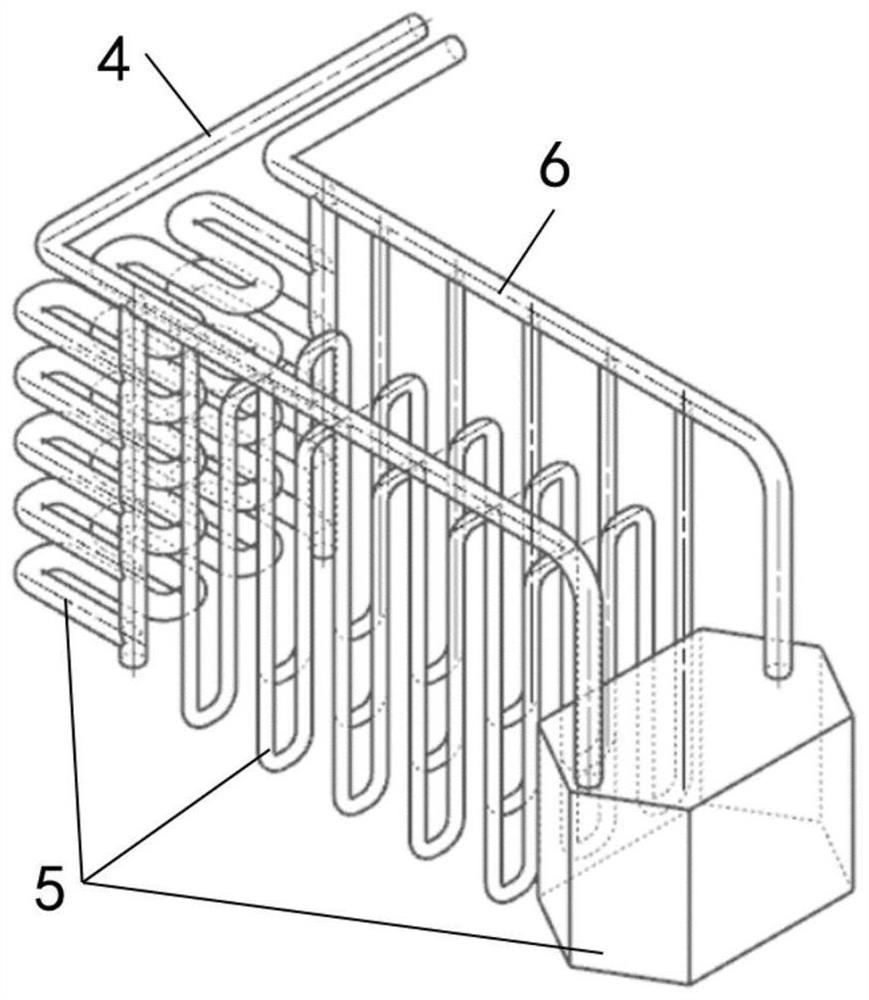
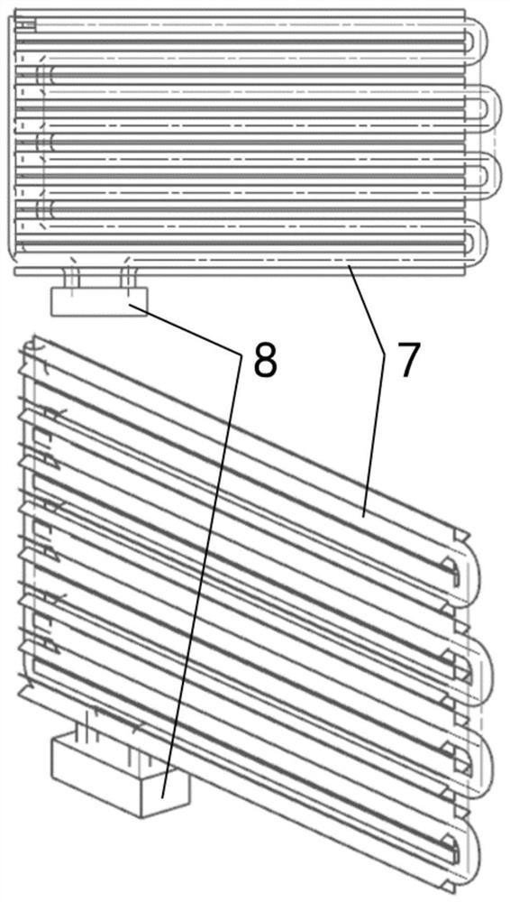
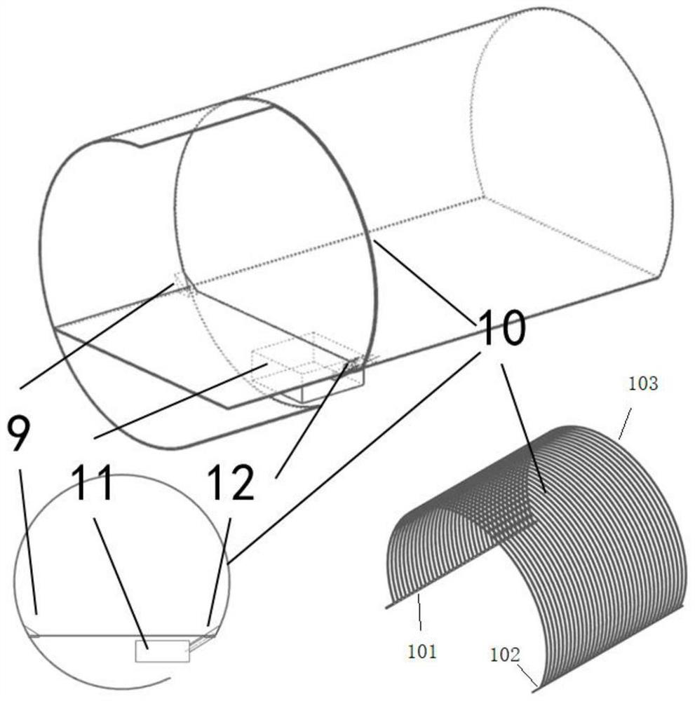
[0024] combine Figure 1-Figure 7 , a kind of air-liquid integrated heat dissipation structure based on the present embodiment of the nearby exhaust aircraft skin radiator, including airborne equipment liquid cooling pipeline 1, air-liquid integrated heat dissipation conversion pipeline 2, cabin air cooling regeneration circuit 3.

[0025] The airborne equipment liquid cooling pipeline 1 includes a liquid supply pipeline 4, each airborne equipment sub-pipeline 5 and a liquid discharge pipeline 6, and the liquid cooling working medium is input into each airborne equipment subpipeline 5 in parallel from the liquid supply pipeline 4, After absorbing heat, they are collected and output to the drain line 6.

[0026] The air-liquid integrated heat dissipation conversion pipeline 2 includes a heat exchange tube 7 with a fin structure and a fluid cir...


PUM


Abstract

The invention discloses a nearby discharging aircraft skin radiator based on a wind-liquid comprehensive heat dissipation structure. The aircraft skin radiator comprises an airborne equipment liquid cooling pipeline, a wind-liquid comprehensive heat dissipation conversion pipeline and an in-cabin air cooling regeneration pipeline. Waste heat generated in the working process of the airborne equipment is absorbed by a liquid-phase refrigerant in the liquid cooling pipeline of the airborne equipment, then is transmitted to air in a cabin through the wind-liquid comprehensive heat dissipation conversion pipeline, is transmitted to an aircraft skin through the air cooling regeneration pipeline in the cabin, and is finally discharged to ambient air. Two heat dissipation modes of liquid cooling heat dissipation and air cooling heat dissipation exist in the aircraft skin heat dissipation device at the same time, the requirement for high heat dissipation heat flux density of the surface of airborne equipment can be met under low power consumption, and the reliability of the aircraft skin heat dissipation device is remarkably improved.

Description

technical field [0001] The invention belongs to the technical field of aircraft flight environment control, in particular to an aircraft skin heat dissipation system based on an air-liquid integrated heat dissipation structure. Background technique [0002] The heat dissipation and cold sources of the aircraft in the high-altitude and high-speed flight environment mainly include: onboard low-temperature fuel, low-temperature ram air introduced from the environment, low-temperature cold sources carried before take-off, low-temperature ducted air drawn from the aeroengine, and low-temperature outside the aircraft skin Air. With the increase of airborne equipment on the aircraft and the increase of heat consumption of a single airborne equipment, the total heat dissipation load of the aircraft has increased significantly. The aircraft environmental control system maintained by the airborne low-temperature fuel is not enough for use. It is necessary to further develop the aircra...

Claims


Application Information

Patent Timeline
Patent Type & Authority Applications(China)
IPC IPC(8): B64C1/38B64C1/12B64D13/08
CPCB64C1/38B64C1/12B64D13/08Y02T50/40
Inventor 李强胡定华林肯
Owner NANJING UNIV OF SCI & TECH
Learn More