Special lifting appliance for rapidly hoisting tin groove bottom bricks of floating glass production line

A technology for tin bath bottom bricks and float glass, which is applied in the directions of transportation and packaging, load hanging components, etc., can solve the problem of long locking and decoupling operation time of tin bath bottom bricks, poor hoisting stability of tin bath bottom bricks, and tin bath bottom bricks. Problems such as the damage of the water chestnut of the bottom brick, to achieve the effect of convenient hooking and decoupling, saving decoupling time, and convenient welding and fabrication

Pending Publication Date: 2019-04-12
广西建工第五建筑工程集团有限公司
View PDF8 Cites 0 Cited by
  • Summary
  • Abstract
  • Description
  • Claims
  • Application Information

AI Technical Summary

Problems solved by technology

Sometimes the position of the sling is not centered, which will lead to poor hoisting stability of the bottom brick of the tin bath and prone to tilting
[0004] 2. The decoupling operation is more troublesome, and it is easy to cause damage to the water chestnut of the tin bath bottom brick. When the tin bath bottom brick is hung on the bottom of the tin bath shell, it is necessary to use a crowbar to pry up the tin bath bottom brick and pull out the soft sling. This process will often damage the edges and corners of the tin bath bottom brick, which will cause certain hidden dangers to the sealing of the tin bath bottom brick
[0005] 3. It takes a long time to lock and unhook the bottom brick of the tin bath, which is inefficient and inconvenient to operate

Method used


Image

  • Special lifting appliance for rapidly hoisting tin groove bottom bricks of floating glass production line
  • Special lifting appliance for rapidly hoisting tin groove bottom bricks of floating glass production line
  • Special lifting appliance for rapidly hoisting tin groove bottom bricks of floating glass production line

Examples


Embodiment Construction

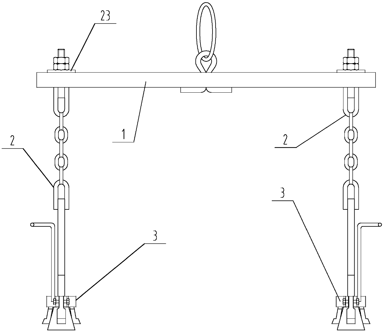
[0037] A special hoisting tool for quick hoisting of tin bath bottom bricks in a float glass production line, such as figure 1 As shown, it includes a main beam part 1, two boom parts 2 and two locking parts 3; each boom part 2 is paired with a locking part 3;

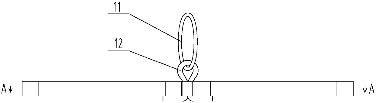
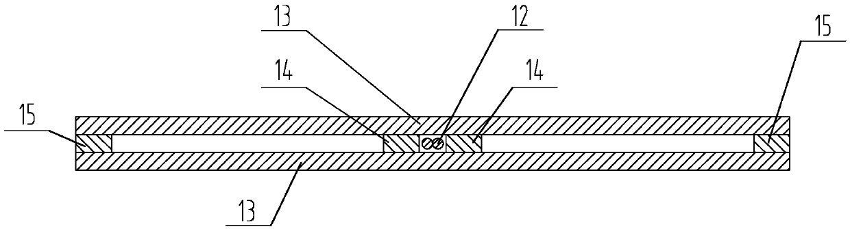
[0038] see figure 2 , image 3 , the main beam component 1 includes a steel wire rope 11, a round steel hook 12, a stressed steel plate 13, a partition steel plate 14 and a limit plate 15;

[0039] The stressed steel plates 13 are arranged symmetrically at parallel intervals, and mainly bear the hoisting load; the round steel hooks 12 are arranged at the parallel central positions of the stressed steel plates 13, and the partition steel plates 14 are symmetrically arranged on both sides of the round steel hooks 12. side and connected with the stressed steel plate 13, the partition steel plate 14 is mainly used to cut off and strengthen the strength of the stressed steel plate 13; the bottom of the round steel hook 1...


PUM


Abstract

A special lifting appliance for rapidly hoisting tin groove bottom bricks of a floating glass production line comprises a main cross beam component, two boom components and two locking components; each boom component is matched with one locking component; the main cross beam component comprises a round steel lifting hook, stress steel boards and an isolation steel board; each boom component comprises a short boom, a U-type round steel lifting hook I, an iron chain, a U-type round steel lifting hook II, a long boom and a conical table; each locking component comprises an execution pull rod, a locking clamping jaw plate and a locking clamping jaw; in an assembly state, the two boom components are symmetrically arranged on two sides of the main cross beam component; the short booms are located in the interval of the two stress steel boards and move in the interval, and the short booms are connected with and hung on the stress steel boards through double nuts; and the long booms penetratethrough the locking jaw plates of the locking components and are connected with the conical tables, so that the locking jaw plates are put on the conical tables in an abutting mode. Hooking and unhooking are convenient and rapid, the phenomena of slant pulling and slant hoisting are avoided in the hoisting process, and the safety performance is high.

Description

technical field [0001] The invention relates to the field of hoisting tools, in particular to a special hoisting tool for quick hoisting of tin bath bottom bricks in a float glass production line. Background technique [0002] With the continuous progress and development of my country's float glass production line construction. Various construction technologies for the construction of float glass production lines have been continuously improved, and construction efficiency has been continuously improved. As one of the three major thermal equipments in the float glass production line, the tin bath is the key equipment to ensure the quality of float glass production, and it is also the core of the float glass forming process. The construction progress and quality of the tin bath bottom brick directly affect the entire float glass production line. The construction period and quality of French glass production line. The number of tin bath bottom bricks is large, and it is nece...

Claims


Application Information

Patent Timeline
Patent Type & Authority Applications(China)
IPC IPC(8): B66C1/12
CPCB66C1/125
Inventor 黄平祖李旭民覃灵学姜兴东陈海东罗丹
Owner 广西建工第五建筑工程集团有限公司
Why Eureka
Try Eureka