
Airflow large-flow field action device and application

A technology of action and airflow, applied in pump devices, lighting devices, lighting devices, etc., can solve the problems of narrow airflow action range, concentrated airflow action direction, exposure of rotating fan blades, etc., to expand the airflow action range, soft and comfortable wind , the effect of improving comfort

Inactive Publication Date: 2019-04-12
曾固
View PDF0 Cites 5 Cited by
  • Summary
  • Abstract
  • Description
  • Claims
  • Application Information

AI Technical Summary

Problems solved by technology

Regardless of whether it is a blower fan or a suction fan, the air flow is formed by the rotation of the rotating blades in the air source body; due to the limitation of the structure of the rotating blades of traditional fans, the range of action of the airflow is limited to the rotation of the rotating blades. The rotating projection range makes the airflow of the traditional fan narrow and the direction of the airflow is concentrated. At the same time, the rotating blades of the traditional fan are exposed, which poses a safety hazard

Method used


Image

  • Airflow large-flow field action device and application
  • Airflow large-flow field action device and application
  • Airflow large-flow field action device and application

Examples


Embodiment 1

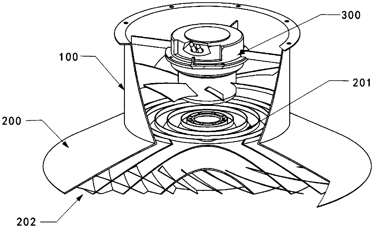
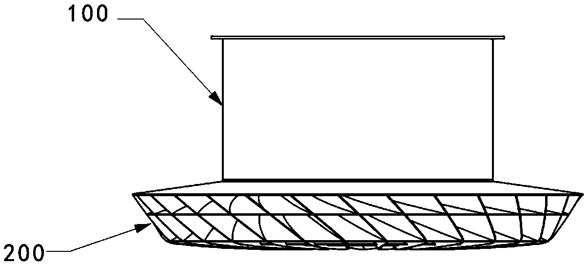
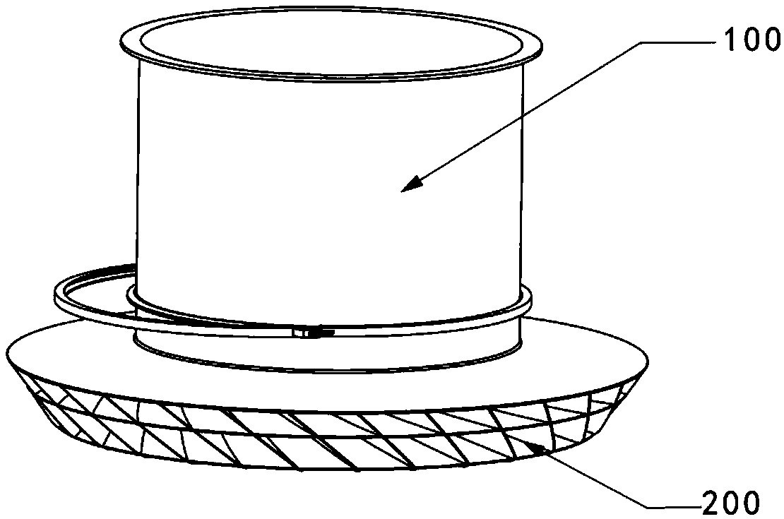
[0130] The working principle of the large air flow field effect device provided in Embodiment 1 when used as a blower fan is: the air at the inlet of the air source body is input from the inlet of the air source body 300 under the action of the air source body 300 and moves along the wind direction. The direction of the axis of the barrel 100 of the source body reaches the wind guide structure 200 to form a single wind bundle; the wind bundle generated by the wind source body 300 enters the corresponding sub-air duct through the first sub-air outlet 201 of each sub-air duct, thereby being divided into A plurality of sub-air bundles, each sub-air bundle is transported to the second sub-air outlet 202 of the sub-air channel along the corresponding sub-air duct, and output to different location spaces of the target air area through the second sub-air outlet 202; the second sub-air outlet 202 The output sub-wind bundle can stimulate the air in the target action area to flow togethe...


PUM


Abstract

The invention relates to the fluid action technology, in particular to an airflow large-flow field action device and application. The airflow large-flow field action device comprises an air source body; and one end of the air source body is provided with an air guide structure body. According to the airflow large-flow field action device, air generated by the air source body is conveyed to different target action air regions by arranging the air guide structure body, or the air in the different target action air regions can be sucked through the air guide structure body, so that the airflow action range of a fan can be effectively expanded; when the device is used as an air supply type fan, the air beam formed by the air source body is divided into a plurality of sub-air beams with different directions through the air guide structure body, air blowing of the air source body is weakened, an air field which is diversified in air blowing direction and soft and comfortable in wind power isformed in the target action air regions, the comfort level can be improved, and meanwhile, people can be prevented from suffering from the electric fan due to long-time air blowing; and due to the fact that the air guide structure body is used for shielding the interior of the air source body, people can not prone to being in contact with fan blades which are rotated at a high speed in the air source body, compared with a traditional fan, the device is safer.

Description

technical field [0001] The invention relates to the technical field of fluid action, in particular to an air flow large flow field action device and its application. Background technique [0002] Traditional fans (or fans) can be divided into two types according to the working nature of their air source body: one is the air supply (or blowing) type fan, and the air source body sends air to the target wind area; the other is the suction fan. Wind (or exhaust) type fan, the wind source body sucks wind to the target action wind area. Regardless of whether it is a blower fan or a suction fan, the air flow is formed by the rotation of the rotating blades in the air source body; the traditional fan is limited to the range of the rotating blades due to the limitation of the structure of the rotating blades. The rotating projection range makes the airflow of the traditional fan narrow and concentrated, and the rotating blades of the traditional fan are exposed, which poses a safety...

Claims


Application Information

Patent Timeline
Patent Type & Authority Applications(China)
IPC IPC(8): F04D25/08F04D29/54F21V33/00F21Y115/10
CPCF04D25/08F04D29/547F21V33/0096F21Y2115/10
Inventor 曾德邻曾固
Owner 曾固
Learn More