Overflow type hydraulic balance valve with vibration damping function

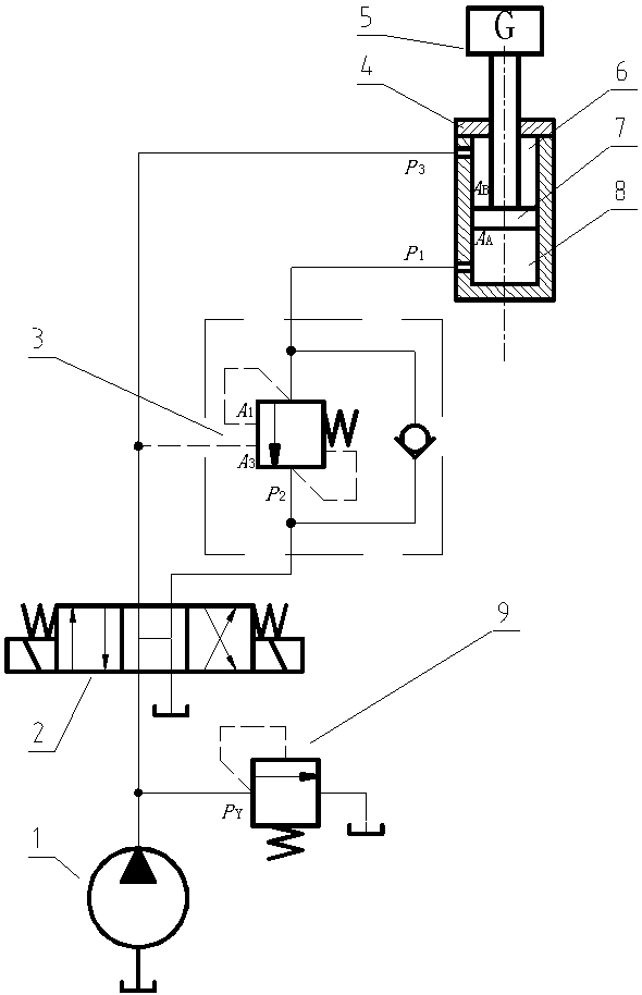
A hydraulically balanced, overflow-type technology, used in fluid pressure actuation devices, servo motors, servo motor components, etc., to solve problems such as the rapid and slow descending of the hydraulic cylinder piston, the vibration of the hydraulic system, and the increase of noise.

Active Publication Date: 2019-04-12
LUOYANG INST OF SCI & TECH
View PDF8 Cites 2 Cited by
  • Summary
  • Abstract
  • Description
  • Claims
  • Application Information

AI Technical Summary

Problems solved by technology

[0046] The purpose of the present invention is to solve the "nod" phenomenon in which the hydraulic cylinder piston descends suddenly and slowly during the working process of the balance valve in the prior art, which will cause vibration of the load and hydraulic system, increase noise, and reduce the reliability of the equipment. problem, as well as reducing the impact of random transient disturbances, reducing the degree of cavitation, and providing a relief type hydraulic balance valve with a damping function

Method used


Image

  • Overflow type hydraulic balance valve with vibration damping function
  • Overflow type hydraulic balance valve with vibration damping function
  • Overflow type hydraulic balance valve with vibration damping function

Examples


Embodiment Construction

[0063] As shown in the figure, the specific implementation method is as follows:

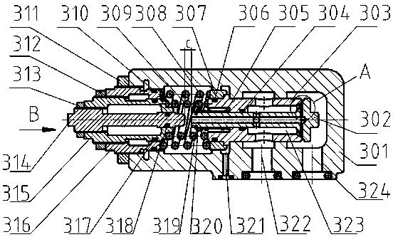
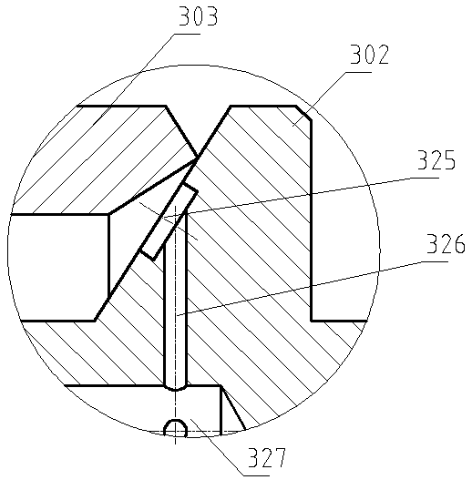
[0064] A relief type hydraulic balance valve with a vibration damping function, comprising a valve body 301, the valve body 301 is provided with an oil inlet chamber 324, an oil outlet chamber 322 and a control oil chamber 321, and a main valve is slid through the valve body 301 Spool 303, the contact surface between the valve body 301 and the main spool 303 adopts clearance fit, the center of the main spool 303 slides through a check spool 302, and the main spool 303 and the check spool 302 run through the oil inlet chamber 324, the oil outlet chamber 322 and the control oil chamber 321, the control oil chamber 321 is not connected with the oil inlet chamber 324 and the oil outlet chamber 322, and the end of the one-way valve core 302 away from the oil inlet chamber 324 is sleeved with a one-way valve core Spring 305, one end of the one-way spool spring 305 presses against the end face of the m...


PUM


Abstract

The invention provides an overflow type hydraulic balance valve with a vibration damping function. The overflow type hydraulic balance valve with the vibration damping function comprises a valve body,wherein a main valve element is slidably arranged in the valve body in a penetrating way; a one-way valve element is slidably arranged in the center of the main valve element in a penetrating way; agap adjusting rod is arranged on the valve body; a gap with adjustable size is arranged between the gap adjusting rod and the one-way valve element; and a control valve element is slidably arranged atone end, far away from an oil inlet cavity, of the valve body in a sleeving way. According to the overflow type hydraulic balance valve with the vibration damping function provided by the invention,under the specific working conditions, through adjusting pretightening forces of two springs, the displacement of the control valve element generated under the oil liquid pressure action of a controloil cavity is larger than the displacement of the main valve element generated under the oil liquid pressure action of the oil inlet cavity, and the opening amount of a balance valve after improvementis promoted to be smaller than the opening amount of a balance valve before improvement, so that the occurrence of the phenomenon of 'nod' is alleviated. Before the gap between the gap adjusting rodand the one-way valve element becomes zero, the one-way valve element and the main valve element do not move relatively, and a valve port of the balance valve cannot be opened, so that the occurrenceof the phenomenon that the system is randomly disturbed instantly so as to enable a load to lose a stationary state is avoided, and the occurrence of a system vibration phenomenon is reduced.

Description

technical field [0001] The invention relates to the field of hydraulic transmission, in particular to an overflow type hydraulic balance valve with vibration damping function. Background technique [0002] In the hydraulic industry, the balance valve is used to maintain the balance state when the negative load moves, and this balance state includes two states of static and uniform motion. In addition to the above two functions, the relief type balance valve also has the function of balancing the pressure overload caused by the inertial force during the sudden change of the load from motion to rest, preventing damage to system components due to excessive overload pressure. Taking gravity as a negative value load as an example, its background technology is described as follows: [0003] 1. The impact of excessive external control pressure on the vibration of the balance system when the hydraulic cylinder piston descends [0004] Such as figure 1 , set the set pressure of ov...

Claims


Application Information

Patent Timeline
Patent Type & Authority Applications(China)
IPC IPC(8): F15B13/02F15B11/08
CPCF15B11/08F15B13/021
Inventor 周天悦
Owner LUOYANG INST OF SCI & TECH
Why Eureka
Try Eureka