Transfer alignment method based on adaptive compensation H infinite filter

An adaptive compensation, transfer alignment technique used in navigation, measuring devices, instruments, etc. via velocity/acceleration measurements

Active Publication Date: 2019-04-12
SOUTHEAST UNIV
View PDF6 Cites 2 Cited by
  • Summary
  • Abstract
  • Description
  • Claims
  • Application Information

AI Technical Summary

Problems solved by technology

This requires dynamic adjustment of the size of the robust factor, so the method of fixing the size o

Method used


Image

  • Transfer alignment method based on adaptive compensation H infinite filter
  • Transfer alignment method based on adaptive compensation H infinite filter
  • Transfer alignment method based on adaptive compensation H infinite filter

Examples


Embodiment Construction

[0106] The technical solutions of the embodiments of the present invention will be described in detail below in conjunction with the accompanying drawings.

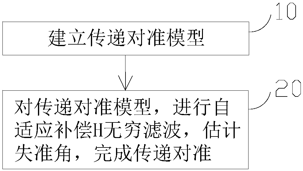
[0107] like figure 1As shown, a transfer alignment method based on adaptive compensation H infinite filtering in an embodiment of the present invention includes:

[0108] Step 10) Build a transfer alignment model.

[0109] Step 20) Perform adaptive compensation H infinite filtering on the transfer alignment model established in step 10), estimate the misalignment angle, and complete the transfer alignment.

[0110] As a preferred example, the step 10) includes:

[0111] Step 101) establish transfer alignment system state equation:

[0112] Select the 12-dimensional state to establish the state vector X(t) of the system, and the system state vector X(t) is shown in formula (1):

[0113]

[0114] Among them, δL represents the latitude error, δλ represents the longitude error, and δV E Indicates the eastward speed er...


PUM


Abstract

The invention discloses a transfer alignment method based on adaptive compensation H infinite filtering. The transfer alignment method comprises the steps: 10) establishing a transfer alignment model;and 20) performing adaptive compensation H infinite filtering on the transfer alignment model established in step 10) to estimate a misalignment angle to complete the transfer alignment. The transferalignment method ensures the stability of a filter in the transfer alignment process and improves the transfer alignment accuracy.

Description

technical field [0001] The present invention relates to a transfer alignment method, in particular to a transfer alignment method based on adaptive compensation H infinite filtering. Background technique [0002] Initial alignment is critical for strapdown inertial navigation systems. A large part of the performance of a strapdown inertial navigation system depends on the speed and accuracy of the initial alignment. According to different alignment modes, initial alignment can be divided into self-alignment, combined alignment and transfer alignment. Compared with self-alignment and combined alignment, the transfer alignment process is faster and the alignment time can be greatly shortened. In transfer alignment, when the precision of the main inertial navigation device is very high, the sub-inertial navigation can obtain higher alignment accuracy. Based on the above advantages, transfer alignment has been widely used in aircraft, ships and vehicles. [0003] Traditional...

Claims


Application Information

Patent Timeline
IPC IPC(8): G01C25/00G01C21/16
CPCG01C21/16G01C25/005
Inventor 程向红吕维维范时秒
Owner SOUTHEAST UNIV
Why Eureka
Try Eureka