Small circular polarizer

A technology of circular polarizers and pins, which is applied to waveguide devices, electrical components, circuits, etc., can solve the problems of high processing accuracy and long length of circular polarizers, and meet the requirements of use and reduce the cost of processing The effect of restricting and guaranteeing performance

Active Publication Date: 2019-04-12
BEIJING INST OF RADIO MEASUREMENT
View PDF6 Cites 2 Cited by
  • Summary
  • Abstract
  • Description
  • Claims
  • Application Information

AI Technical Summary

Problems solved by technology

This will result in a longer circular polarizer length and higher requirements for machining accuracy

Method used


Image

  • Small circular polarizer
  • Small circular polarizer
  • Small circular polarizer

Examples


Embodiment Construction

[0030] In order to make the purpose, technical solutions and advantages of the embodiments of the present invention clearer, the technical solutions of the present invention will be clearly and completely described below in conjunction with the accompanying drawings. The described embodiments are part of the embodiments of the present invention, not all of them. example.

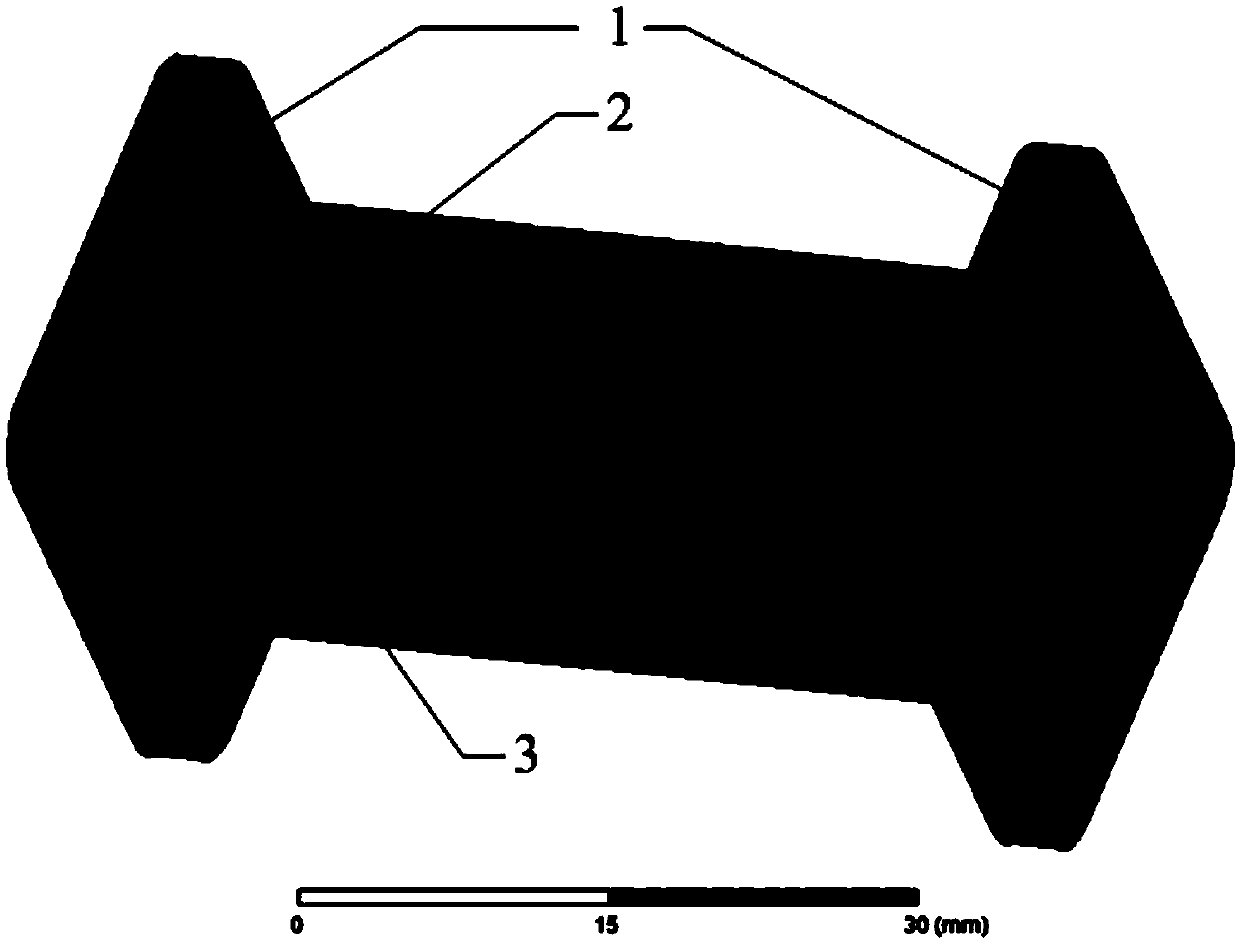
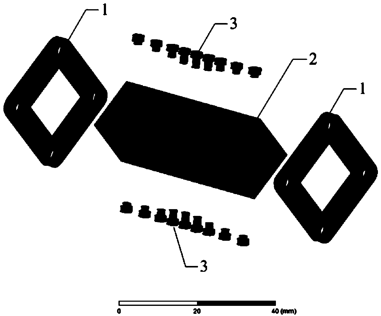
[0031] Such as figure 1 with figure 2 As shown, 1. A miniaturized circular polarizer provided by the embodiment of the present invention includes a flange 1, a square waveguide cavity 2 and a set of pins 3, the flange 1 is installed at both ends of the square waveguide cavity 2, and the set of pins 3 is set On the edge of the square waveguide cavity 2.

[0032] In an optional embodiment, the square waveguide cavity 2 is formed by machining an aluminum block.

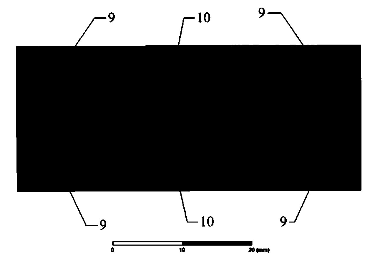
[0033] Such as image 3 with Figure 4 As shown, the gradient cut angle 9 is set on the edge of the square waveguide cavity 2 where the pin set ...


PUM


Abstract

The invention discloses a small circular polarizer. The small circular polarizer comprises flanges, a square waveguide cavity and large-diameter pin sets, wherein the flanges are installed at the twoends of the square waveguide cavity, the pin sets are arranged on edges of the square waveguide cavity, gradient corner cuts are arranged at the edges, where the pin sets are located, of the square waveguide cavity, and the gradient corner cuts are located at near ports of the square waveguide cavity; isobathic corner cuts are arranged at the edges, where the pin sets are located, of the square waveguide cavity; isobathic corner cuts are arranged at edges, where the pin sets are not located, of the square waveguide cavity; and each pin set comprises at least one group of pins, wherein each group of pins comprises an even number of pins with the same length, and distances between the adjacent pins in each pin set are not equal. The square waveguide cavity is formed by machining an aluminumblock, and the gradient corner cuts and the isobathic corner cuts are machined by the adoption of an electrosparking method. The insertion depth, in the edges of the square waveguide cavity, of the pins in the pin sets is successively decreased from the middle to the two ends. Through the proposed technical scheme, the technical effects of reducing circular polarizer size and lowering machining limitation are achieved.

Description

technical field [0001] The present invention relates to a miniaturized circular polarizer, more specifically, relates to a miniaturized circular polarizer with Ku frequency band, wide frequency band, large diameter, pin loading with unequal spacing. Background technique [0002] The waveguide circular polarizer is a key component of the circularly polarized reflector antenna feed system, and its main function is to transform linearly polarized signals into circularly polarized signals. The structural form of the waveguide circular polarizer directly determines the volume, weight and electrical performance of the feed horn. Common forms of circular polarizers include square waveguide or circular waveguide inserting diaphragms, ridges, pins or dielectric plates and other phase-shifting element structures, as well as grooves on the symmetrical wall of the circular waveguide, cutting corners of the square waveguide, and circular polarizers. The waveguide transitions directly to...

Claims


Application Information

Patent Timeline
Patent Type & Authority Applications(China)
IPC IPC(8): H01P1/17H01Q15/24
CPCH01P1/17H01Q15/24
Inventor 刘德文
Owner BEIJING INST OF RADIO MEASUREMENT
Why Eureka
Try Eureka